Ice-making device

a technology of ice-making device and ice-making device, which is applied in the direction of ice production, refrigeration machine, machine using electric/magnetic effect, etc., can solve the problems of large ice-making device and large ice-making devi

Inactive Publication Date: 2006-08-03
PANASONIC CORP
View PDF3 Cites 99 Cited by
  • Summary
  • Abstract
  • Description
  • Claims
  • Application Information

AI Technical Summary

Benefits of technology

[0025] An ice-making device of the present invention comprises an ice-making unit for making a plank-shaped block of ice, cracking means for cracking the plank-shaped block of ice produced in the ice-making unit into a plurality of ice chips within

Problems solved by technology

There was also a drawback that the ice-making device becomes quite bulky in size since the rotors must have dimensions enough to hold a block of plank-shaped ice, and the ice-making unit and the conveyer unit need respectively large

Method used


Image

  • Ice-making device
  • Ice-making device
  • Ice-making device

Examples


first exemplary embodiment

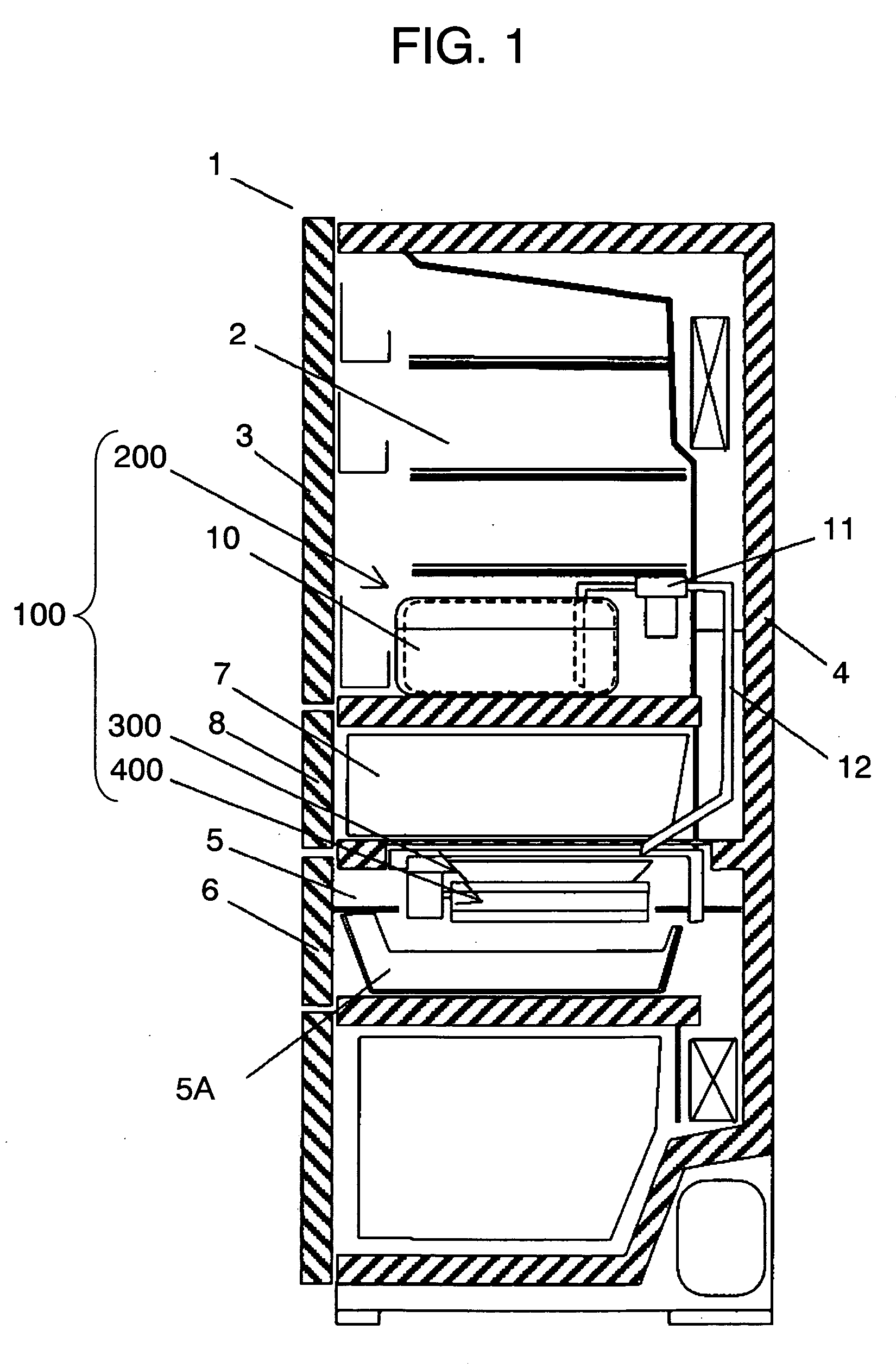
[0056] Referring now to FIG. 1 through FIG. 4, description is provided of the first exemplary embodiment.

[0057] Refrigerator / freezer's main cabinet 1 (hereinafter referred to as main cabinet 1) has a plurality of storage compartments, of which first refrigerator compartment 2 formed in the upper part of it is enclosed and thermally insulated from the external air by door 3 and insulation wall 4. Freezer compartment 5 (hereinafter referred to as ice-making compartment 5) formed under first refrigerator compartment 2 is enclosed and thermally insulated from the external air by insulation wall 4 and door 6. Ice storage box 5A for storing ice cubes is disposed to the lower space of ice-making compartment 5. Second refrigerator compartment 7 located between first refrigerator compartment 2 and ice-making compartment 5 is enclosed and thermally insulated from the external air by insulation wall 4 and door 8. First refrigerator compartment 2 and second refrigerator compartment 7 are conne...

second exemplary embodiment

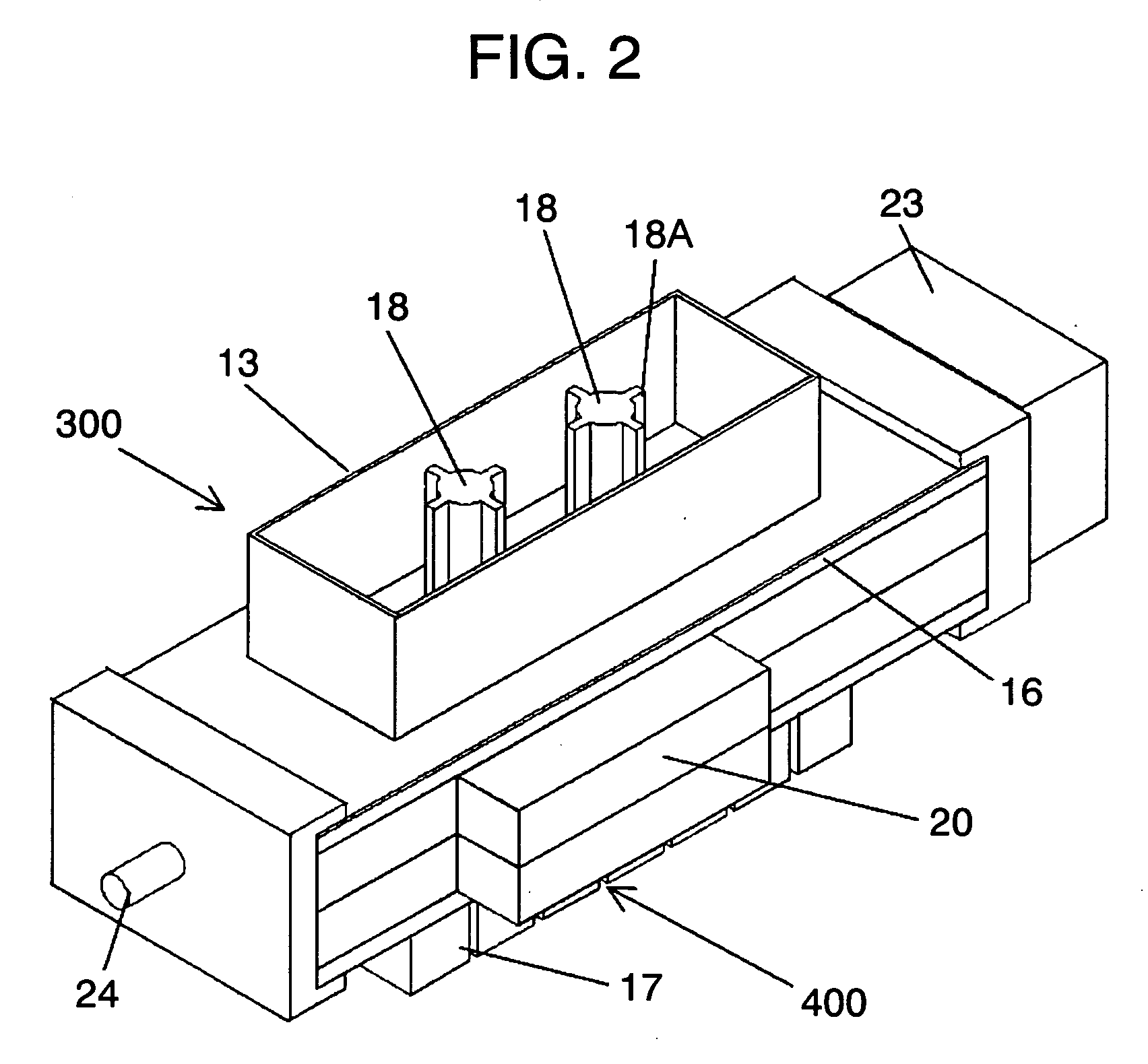
[0084] Description is provided of an ice-making device of the second exemplary embodiment with reference to FIG. 5 through FIG. 7.

[0085] Like reference numerals are used to designate like components as those of the first exemplary embodiment, and details of them will be skipped.

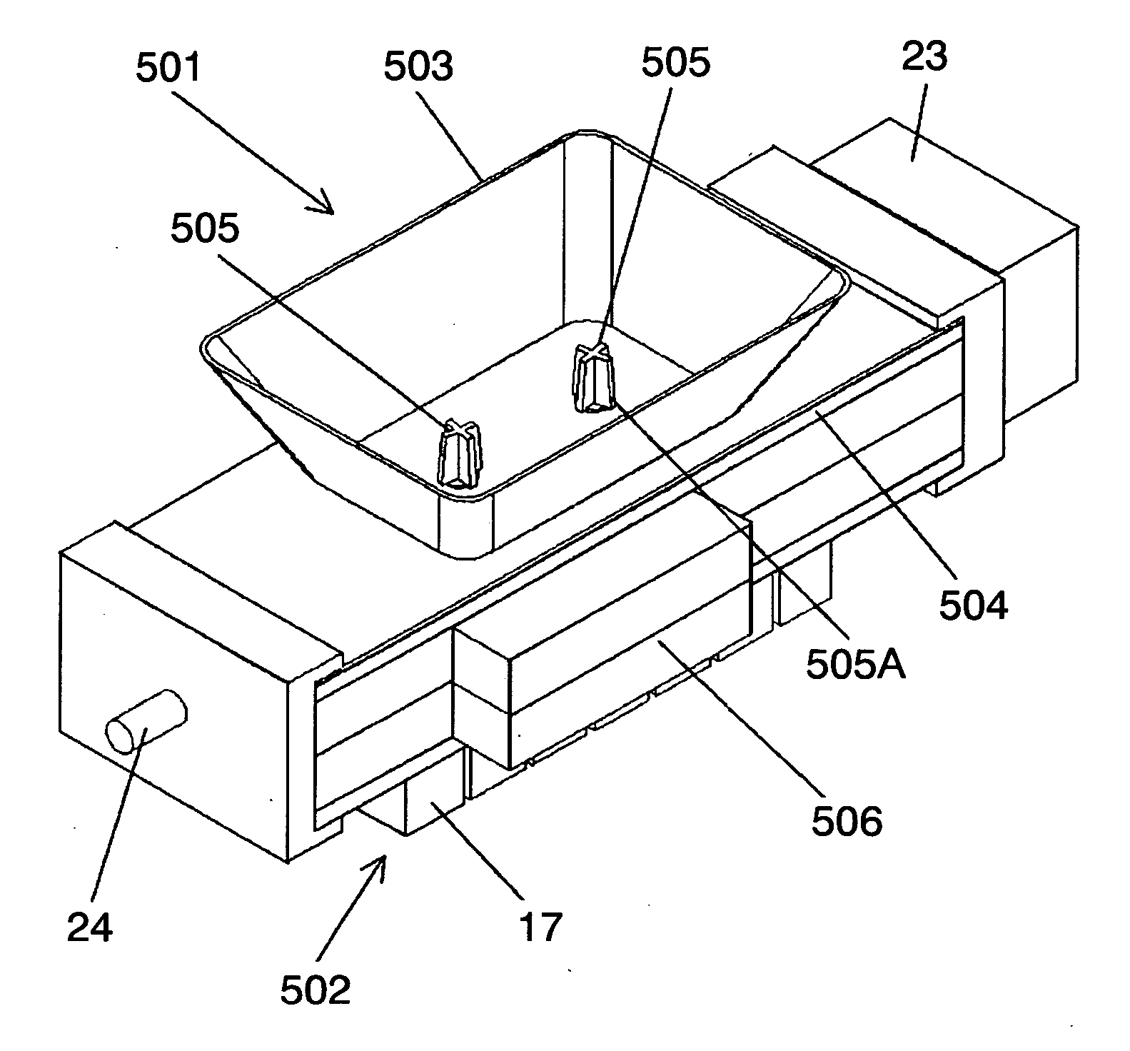
[0086] Ice-making device 100 comprises water supply unit 200, ice-making unit 501, and ice-cracking unit 502 for use as ice-cracking means

[0087] Ice-making unit 501 comprises ice-making vessel 503 having an open top and open bottom with side surfaces sloped in a direction to make the top opening larger in area than an area of the bottom opening, for temporarily storing water and making a plank-shaped block of ice, cooling plate 504 fixed to ice-making vessel 503 in a manner that one side surface comes into close contact to and composes a bottom wall of ice-making vessel 503 and the other side surface is in close contact to one surface of Peltier device 14 via heat conduction member 15, and heat sink 17 bon...

third exemplary embodiment

[0101] Description is provided of ice-making device 100 of the third exemplary embodiment with reference to FIG. 1 and FIG. 8 through FIG. 10. Like reference numerals are used to designate like components as those of the first exemplary embodiment, and details of them will be skipped.

[0102] Refrigerator / freezer's main cabinet 1 (hereinafter referred to as main cabinet 1) has a plurality of storage compartments, and first refrigerator compartment 2 formed in the upper part of it is enclosed and thermally insulated from the external air by door 3 and insulation wall 4. Freezer compartment 5 (hereinafter referred to as ice-making compartment 5) formed under first refrigerator compartment 2 is enclosed and thermally insulated from the external air by insulation wall 4 and door 6. Ice storage box 5A for storing ice chips is disposed to the lower space of ice-making compartment 5. Second refrigerator compartment 7 located between first refrigerator compartment 2 and ice-making compartmen...


PUM


Abstract

A compact ice-making device is provided for making ice chips of varied shapes for use in glasses of whiskey and water, and the like purposes. Ice is made using an ice-making vessel (13) for making a plank-like block of ice with a shaft (18) inserted in advance in the vessel, the shaft (18) having ribs (18A) extending substantially radially from a rotating axis. Upon completion of the ice making, a gear unit (20) connected to the shaft (18) is driven by a motor to rotate the shaft (18), which cracks and divides the plank-like ice block into ice chips of varied shapes.

Description

TECHNICAL FIELD [0001] The present invention relates to an ice-making device capable of making ice chips of varied shapes. BACKGROUND ART [0002] In household refrigerators and the like, there has hitherto been a wide use of automatic ice-making device (hereinafter referred to as ice-making device) for storing and freezing water supplied from a water-supply pipe into an ice-making vessel, and releasing the produced ice cubes by means of a drive unit which turns the ice-making vessel upside down. [0003] Description is provided hereinafter of one such ice-making device of the prior art with reference to the accompanying drawings. FIG. 26 shows an overall structure of the ice-making device in the conventional refrigerator. [0004]FIG. 27 is a structural illustration of an ice-making unit of the conventional ice-making device. As shown in FIG. 26 and FIG. 27, main cabinet 75 of the refrigerator comprises outer cabinet 76, inner cabinet 77, and insulating material 78 filled in a space betw...

Claims


Application Information

Patent Timeline
IPC IPC(8): F25C1/00F25C1/22F25B21/02F25C1/10F25C5/04F25C5/14
CPCF25B21/02F25C1/10F25C5/04F25C5/14F25C2500/08F25C1/25F25C1/20F25C5/142
Inventor TATSUI, HIROSHIADACHI, TADASHIISHITA, MITOKOKAMISAKO, TOYOSHI
Owner PANASONIC CORP
Why Eureka
Try Eureka