Differential pressure sensor

a technology of differential pressure sensor and liquid pressure, which is applied in the direction of fluid pressure measurement using capacitance variation, instruments, measurement devices, etc., can solve the problems of high probability of measurement error, difficult to achieve the completely equal levels of influence of intricate deformation of each of the two diaphragms, and difficult detection of differential pressure. high accuracy and sensitive

Inactive Publication Date: 2006-08-03
MKS JAPAN
View PDF9 Cites 8 Cited by
  • Summary
  • Abstract
  • Description
  • Claims
  • Application Information

AI Technical Summary

Benefits of technology

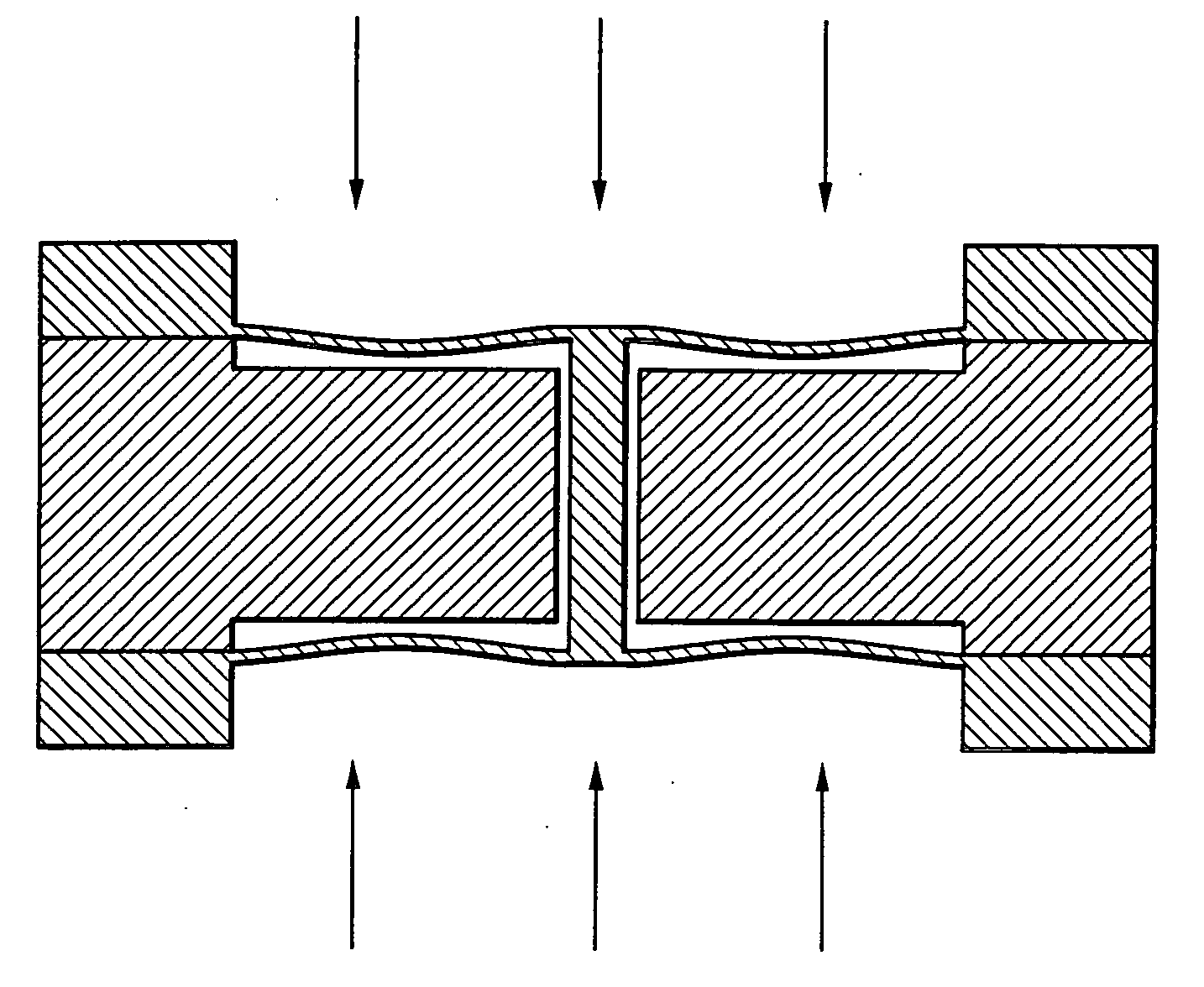
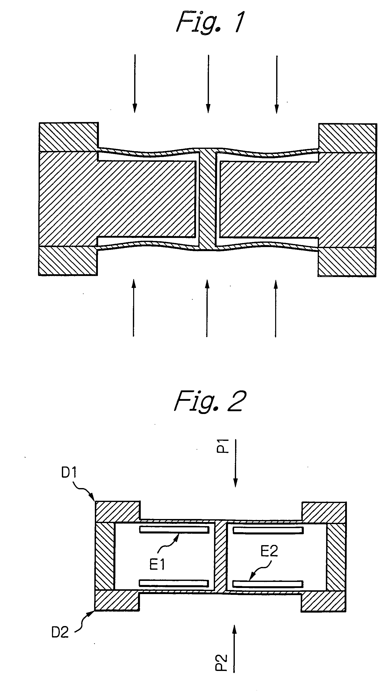
[0016] In the present invention, differing from a conventional technique, a capacitor electrode is not formed by the diaphragm itself, but is formed by the movable electrode disposed between the two diaphragms. Since opposite sides of the movable electrode are pressed under equal forces through the diaphragms, a position of the movab...

Problems solved by technology

In this method, however, a measurement error is likely to occur when the characteristics of the two sensors are not truly identical.
Although both of the diaphragms are subject to intricate deformation, it is extremely difficult to achieve the completely equal levels of influence of intricate deformation of each of the ...

Method used


Image

  • Differential pressure sensor
  • Differential pressure sensor
  • Differential pressure sensor

Examples


Embodiment Construction

[0027] Herein below, description is made with regard to a preferred embodiment of the present invention. FIG. 4 is a sectional view of a differential pressure sensor according to an embodiment of the present invention. FIG. 5 is a disassembled sectional view of the differential pressure sensor of FIG. 4. In FIG. 4, a pair of metal diaphragms 1a and 1b having the same outer shape is provided. The diaphragms 1a and 1b respectively comprise cylindrical projections 6a and 6b formed at central portions thereof. Thin and flat diaphragm portions 7a and 7b in annular forms are formed along the peripheries of the cylindrical projections 6a and 6b, respectively. Cylindrical support portions 8a and 8b are respectively formed along the outer peripheries of the diaphragm portions 7a and 7b. From the viewpoint of mechanical life, it is preferred that the diaphragms 1a and 1b are made of an alloy of Ni or an alloy of Ti. However, the diaphragms 1a and 1b can be formed from a non-metal material suc...


PUM


Abstract

According to the present invention, there is provided a high-precision differential pressure sensor which is not affected by a considerable change in baseline pressure. A differential pressure sensor of the present invention comprises: a pair of diaphragms, each including a diaphragm portion capable of being deformed due to application of a pressure and a support portion for holding an outer peripheral edge of the diaphragm portion; a pair of fixed electrodes in disk-like form fixed to the support portions of the diaphragms; and a movable electrode including a disk-like electrode portion and shaft-like projections extending in opposite directions from a central portion of the electrode portion. The shaft-like projections extend at a right angle relative to the electrode portion, and the movable electrode is secured to central portions of the diaphragms through the shaft-like projections so that the electrode portion faces each of the fixed electrodes in a predetermined spaced relationship. The movable electrode is capable of moving so as to allow a distance between the electrode portion and each of the fixed electrodes to vary according to a difference between fluid pressures acting on the respective diaphragm portions of the diaphragms. A capacitance generated between the electrode portion and each of the fixed electrode changes due to a variance in the distance between the electrode portion and each of the fixed electrode, and a differential pressure is detected, based on this change in capacitance.

Description

BACKGROUND OF THE INVENTION [0001] The present invention relates to a sensor for measuring a differential pressure of liquids and the like. [0002] As a sensor for measuring a pressure of a liquid, use is made of a diaphragm-type pressure sensor so as to avoid a sensor portion being adversely affected by a liquid to be measured. As a method for measuring a differential pressure of two liquids, there is a method of using two diaphragm-type pressure sensors, in which a differential pressure is determined from a difference between outputs of the two sensors. In this method, however, a measurement error is likely to occur when the characteristics of the two sensors are not truly identical. [0003] U.S. Pat. No. 6,640,640B2 and U.S. Pat. No. 6,431,003B1 disclose a sensor comprising two diaphragms disposed so as to face each other and which are connected to each other by means of a rod. In this sensor, a pressure applied to one diaphragm is transmitted to the other diaphragm. Therefore, onl...

Claims


Application Information

Patent Timeline
IPC IPC(8): G01L13/02
CPCG01L9/0072G01L13/025
Inventor SUZUKI, ISAO
Owner MKS JAPAN
Why Eureka
Try Eureka