Friction stir welding method

a friction stir and welding method technology, applied in the field of friction stir welding method, can solve the problems of heat deformation of the panel (members), deterioration of the appearance, and high work intensity, and achieve good friction stir

Inactive Publication Date: 2006-08-03
HITACHI LTD
View PDF16 Cites 24 Cited by
  • Summary
  • Abstract
  • Description
  • Claims
  • Application Information

AI Technical Summary

Benefits of technology

[0012] The first object of the present invention is to provide a good friction stir weld joint upon welding a butted portion between two members.
[0013] Further, the second object of the present invention is to create a good friction stir weld joint upon welding a butted portion between two members having different thicknesses.

Problems solved by technology

Furthermore, as shown in patent document 1, it is not possible to obtain a good joint if a space exists at the butted portion between the two members, so extruded shape members having projections formed to the butted portions are butted against one another, and friction stir welding is performed so that the metal material constituting the projection is filled in the space formed at the butted portion.
However, in this case, since deposit welding is performed manually, it requires much work.
Further, black marks are adhered to the surface of the members during the welding process, which deteriorates the appearance, and the weld heat may deform the panel (members).
In this arrangement, a defect is likely to occur in the friction stir weld bead.
It is possible to form a friction stir weld joint eliminating such defects, but since the conditional range of such friction stir welding is narrow, it is extremely difficult to perform such welding.
In this case, the thinner panel is positioned to overlap with the protruded block on the thicker panel, but if there is a space formed between the upper surface of the protruded block and the lower surface of the thinner panel, a defect is likely to occur in the friction stir weld bead.

Method used


Image

  • Friction stir welding method
  • Friction stir welding method
  • Friction stir welding method

Examples


embodiment 1

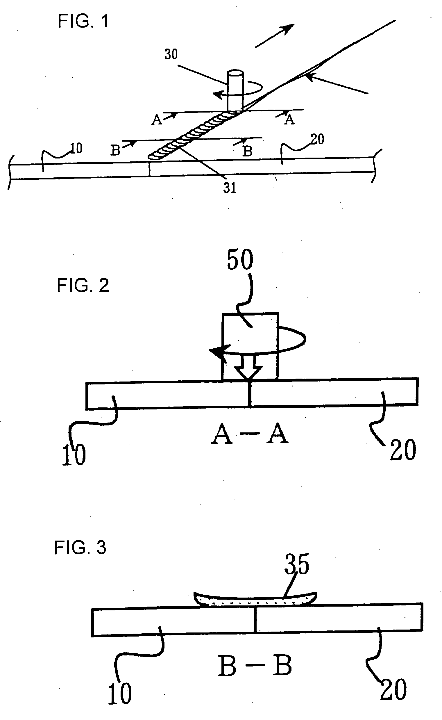
[0026] Now, the present invention will be described with reference to FIGS. 1 through 3. In FIG. 1, panels 10 and 20 are butted against each other. The material of the panels 10 and 20 is aluminum alloy. The back sides of the panels 10 and 20 are placed on a base (not shown).

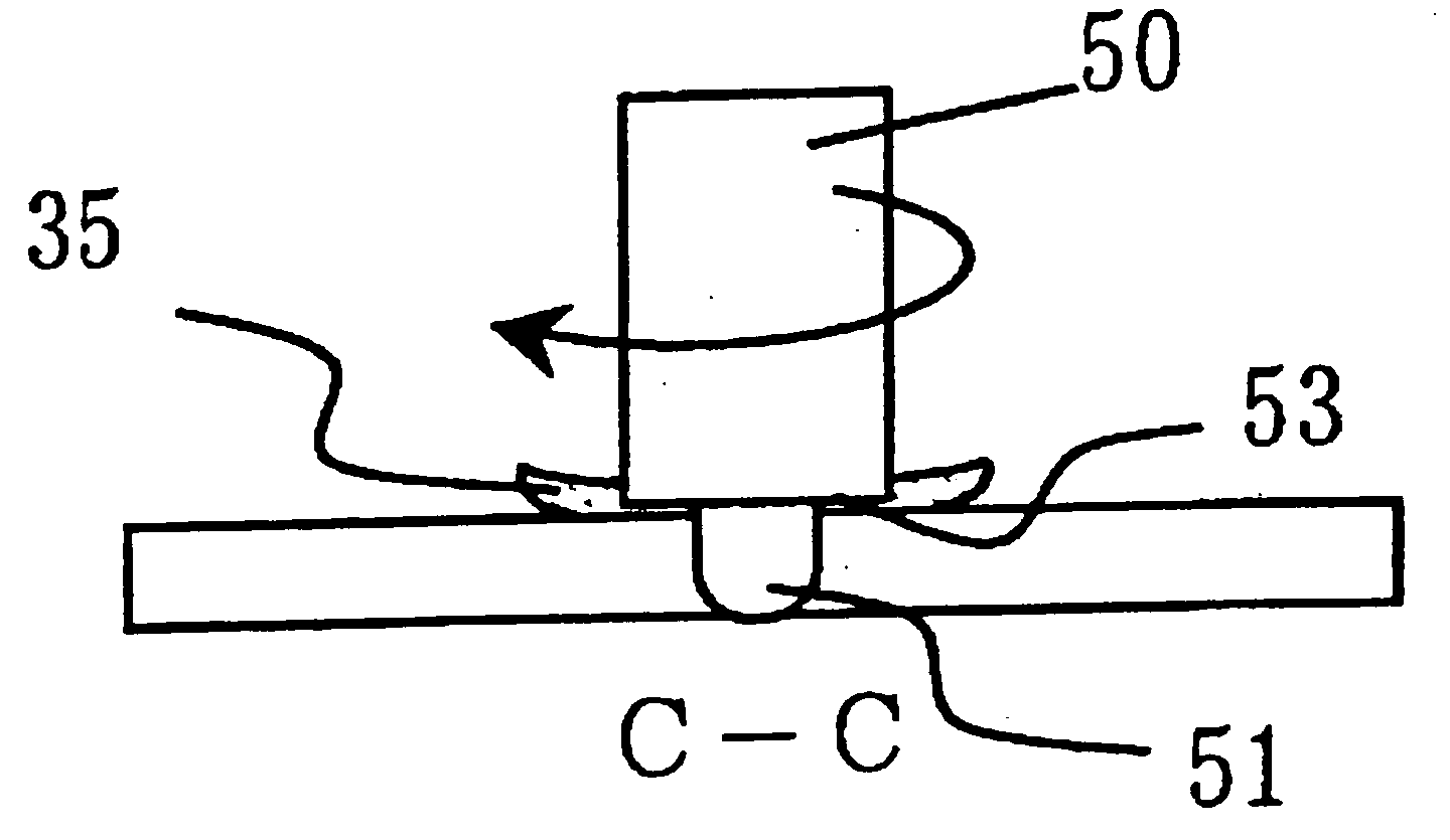
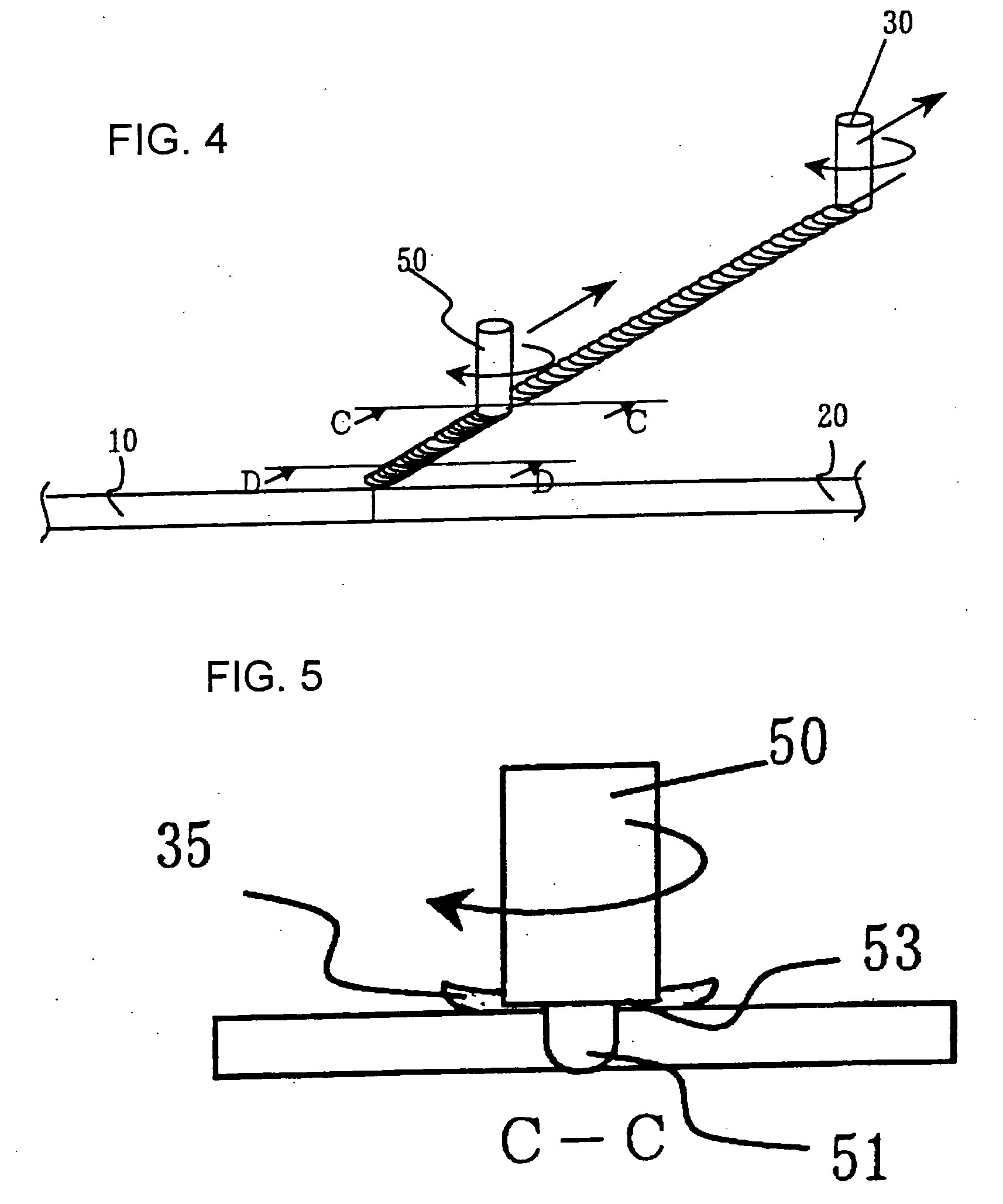
[0027] In this state, at first, a buildup member 30 is pressed on the upper surface of the butted portion from above, and the buildup member is rotated and relatively moved along the butted portion. The buildup member 30 is a round bar which is made of aluminum alloy material similar to panels 10 and 20. Thereby, a buildup bead 35 is welded to the upper surface of the butted portion along with the movement of the buildup member 30.

[0028] By the buildup member 30 being transferred as the buildup bead 35, the buildup member 30 becomes short, and at an appropriate timing, the rotation and movement of the buildup member is stopped, and the consumed buildup member is replaced with a new buildup member having a pred...

embodiment 2

[0048] Embodiment 2 will now be described with reference to FIG. 7. Friction stir welding is carried out in the order of (A), (B), (C) and (D) of FIG. 7. Member 70 is an extruded shape member having a protruded block 71 for placing a member 60. The member 60 can also be an extruded shape member. The member 60 is placed on the protruded block 71 of the member 70, and thus the members 60 and 70 are butted against each other. The upper surface of the member 70 near the butted portion is higher than the upper surface of the member 60. The plate thickness of the member 60 is thinner than the plate thickness of the member 70. The member 70 is placed on a base (not shown).

[0049] After assembling the members as described above, at first, a buildup member 30 is used to bond a buildup bead 35 to the upper surface of the member 60. Thus, a buildup bead 35 is welded to the upper surface of the member 60. The buildup bead 35 is welded to the upper surface of the member 60 and the side end of th...


PUM

PropertyMeasurementUnit
thicknessaaaaaaaaaa
diameteraaaaaaaaaa
outer diameter sizeaaaaaaaaaa

Abstract

The invention provides a friction stir welding method with less weld defects upon welding a butted portion between a first member and a second member. A first member 10 is butted against a second member 20, and then a round-bar buildup member 30 is pressed against the upper surface of the butted portion and rotated to weld a buildup bead 35 thereon. The buildup bead corresponds to a projection of the prior art friction stir welding method. Next, a pin 51 of the rotary tool 50 is inserted to the butted portion to perform friction stir welding. According to this method, the buildup bead 35 corresponds to a projection and fills the space formed to the butted portion, so a good weld joint is formed and the generation of defects is suppressed.

Description

[0001] The present application is based on and claims priority of Japanese patent application No. 2005-24696 filed on Feb. 1, 2005, the entire contents of which are hereby incorporated by reference. BACKGROUND OF THE INVENTION [0002] 1. Field of the Invention [0003] The present invention relates to a friction stir welding method for welding two members. More specifically, it relates to a friction stir welding method for welding two members butted against each other. [0004] 2. Description of the Related Art [0005] A friction stir welding method is disclosed in Japanese Patent No. 03014654 (U.S. Pat. No. 6,581,819) (patent document 1). As disclosed in patent document 1, a friction stir welding method relates to inserting a rotary tool to a butted portion between two members, rotating the rotary tool to soften the members and to perform solid-phase welding of the members. [0006] In general, a friction stir welding method is performed by butting together panel members having the same th...

Claims


Application Information

Patent Timeline
Patent Type & Authority Applications(United States)
IPC IPC(8): B23K20/12B23K31/02
CPCB23K20/1215B23K20/122B23K20/128B23K2201/045B23K2101/045
Inventor EZUMI, MASAKUNIOKADA, NORIHISA
Owner HITACHI LTD
Why Eureka
Try Eureka