Arc tube array-type display device and driving method thereof

a display device and array technology, applied in the direction of discharge tube luminescnet screens, instruments, gas exhaustion means, etc., can solve the problems of high discharging voltage, increased shielding rate, and insufficient supply of vacuum ultraviolet rays to be used for exciting, so as to achieve superior arc tube array-type display, reduce the shielding rate of light projected from the arc tube array, and reduce the discharging voltage between the display electrodes

Inactive Publication Date: 2006-08-03
SHINODA PLASMA
View PDF1 Cites 6 Cited by
  • Summary
  • Abstract
  • Description
  • Claims
  • Application Information

AI Technical Summary

Benefits of technology

[0013] In accordance with the present invention, the discharge between the display electrodes is prepared as an opposing discharge. Therefore, in comparison with an arc tube array-type display device in which the discharge between the display electrodes is prepared as a face discharge, the discharge voltage between the display electrodes can be lowered, and the number of electrodes

Problems solved by technology

In the arc tube array of this electrode layout, however, since the display discharge is prepared as a face discharge, a high discharging voltage is required.
Moreover, the phosphor layer is formed on the back surface side of the inside of the arc tube, and since the area of the face discharge is apart from this phosphor layer, vacuum ultraviolet rays to be used for exciting are not sufficiently supplied to the phosphor layer.
Moreover, since two display electrodes are placed at a single light-emitting ar

Method used


Image

  • Arc tube array-type display device and driving method thereof
  • Arc tube array-type display device and driving method thereof
  • Arc tube array-type display device and driving method thereof

Examples


Embodiment Construction

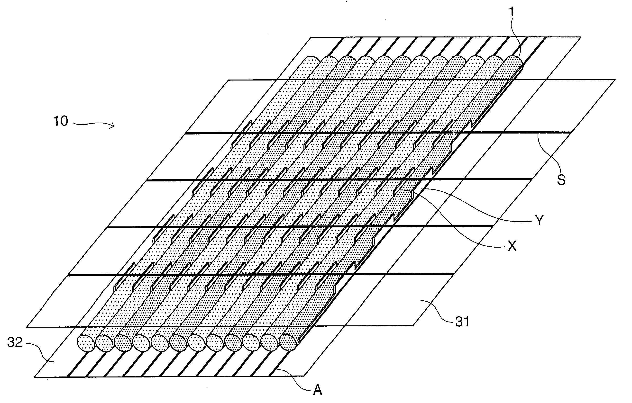
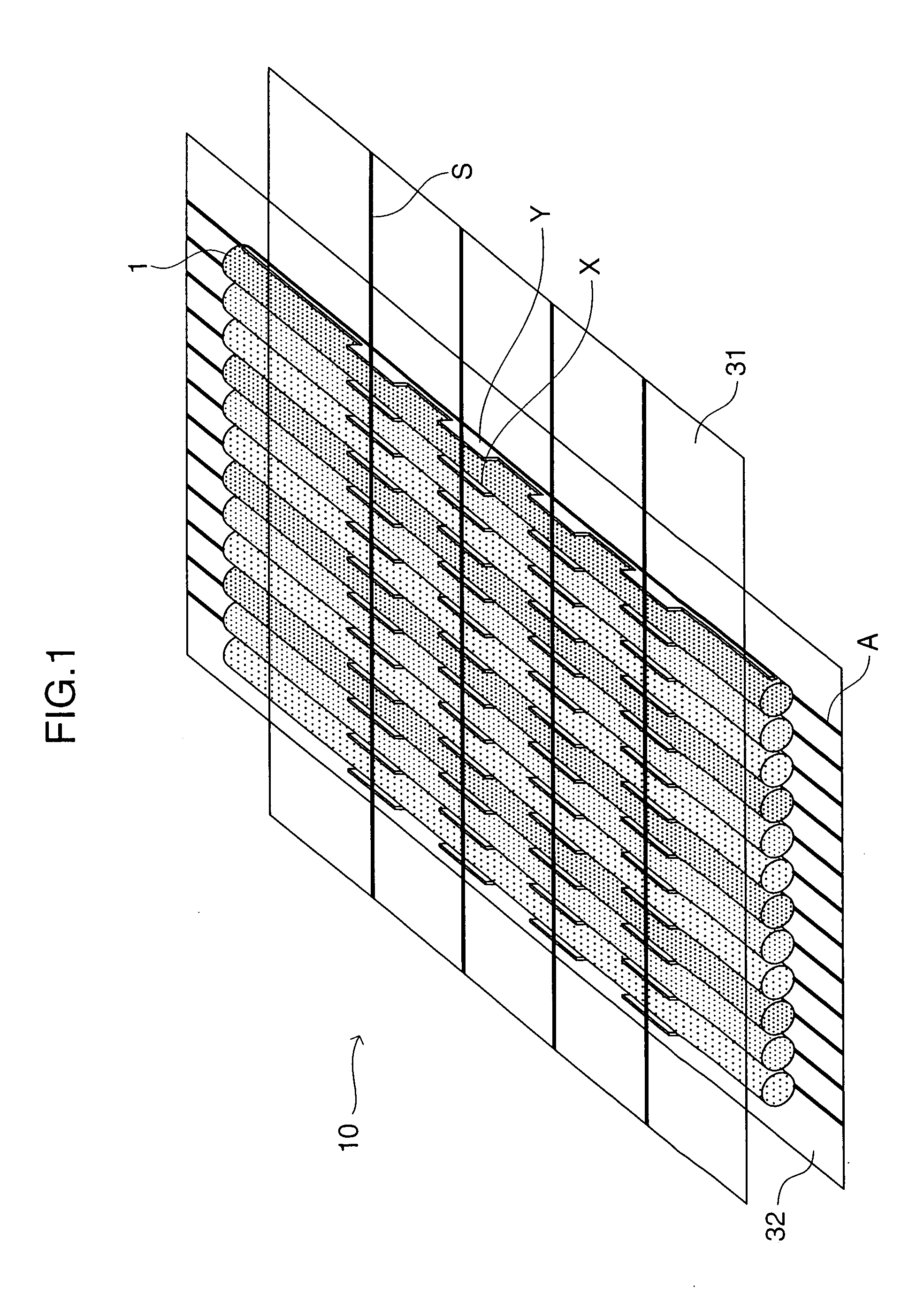
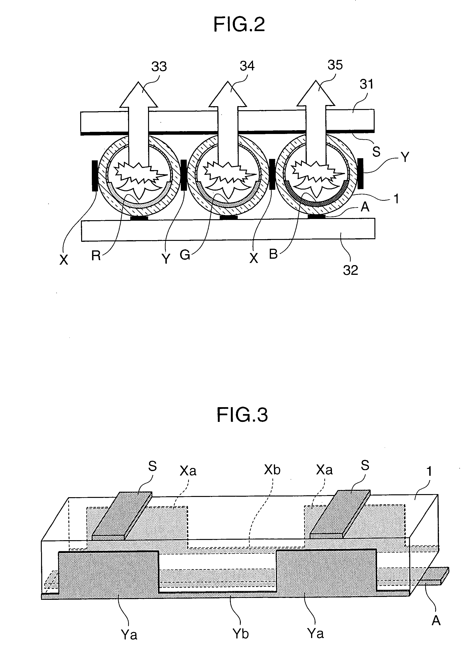
[0032] In the arc tube array-type display device of the present invention, any arc tube array may be used as long as it has a structure in which a plurality of arc tubes, each having a discharge gas sealed therein, are arranged side by side. With respect to a thin tube that forms the tube body of the arc tube, any thin tube having any diameter may be used, and preferably, those tubes having a diameter in a range from 0.5 to 5 mm, made of glass, are adopted. With respect to the shape of the thin tube, any sectional shape, such as a round shape in its section, a flat elliptical shape in its section and a rectangular shape in its section, may be used.

[0033] With respect to the supporting member, any member may be used as long as it is made in contact with at least one of the display surface side and the back surface side of the arc tube array, and can support the arc tube array. For example, a flexible sheet made of resin and a substrate made of glass may be used as the supporting mem...


PUM


Abstract

An arc tube array-type display device includes an arc tube array, a supporting member, a plurality of display electrodes, a plurality of scan electrodes, and a plurality of address electrodes. The arc tube array has a plurality of arc tubes arranged side by side. Each of the arc tubes has a discharging gas sealed therein. The supporting member supports the arc tube array. The plurality of display electrodes are arranged at an adjacent portion between the arc tubes, and generate an opposing discharge inside the arc tube by applying voltages to each of the arc tubes from both of the side faces. The plurality of scan electrodes are arranged on the display surface side of the arc tube in a stripe form in a direction intersecting the longitudinal direction of the arc tube so as to form light-emitting areas at intersecting portions against the arc tubes. The plurality of address electrodes are used for selecting light-emitting areas arranged on the back surface side of the respective arc tubes.

Description

FIELD OF THE INVENTION [0001] The present invention relates to an arc tube array-type display device and its driving method, and more particularly concerns an arc tube array-type display device in which a plurality of arc tubes (also referred to as “display tube” and “gas discharge tube”), each formed of a thin tube of about 0.5 to 5 mm in diameter in which a phosphor layer is placed with a discharge gas sealed therein, are aligned in parallel with one another to display a desired image, and its driving method. BACKGROUND ART [0002] With respect to the arc tube array-type display of this type, those disclosed in Japanese Patent Application Laid-Open No. 2003-86141 and Japanese Patent Application Laid-Open No. 2003-86142 have been known. FIGS. 17 and 18 show these examples. FIG. 18, which is a partial cross-sectional view of FIG. 17, shows a state in which a display device is cut in a direction orthogonal to the length direction of the arc tube of a display device. [0003] In this arc...

Claims


Application Information

Patent Timeline
IPC IPC(8): H01J1/62H01J63/04G09G3/20G09G3/28G09G3/288G09G3/291G09G3/292G09G3/293G09G3/294H01J11/12H01J11/16H01J11/18H01J11/24H01J11/26H01J11/32H01J11/36H01J11/38H01J11/40H01J11/42H01J11/50H01J11/54
CPCG09G3/2803G09G3/2927G09G3/294G09G3/2986G09G2310/066G09G2320/0228H01J11/18H01J11/24H01J11/32
Inventor HIRAKAWA, HITOSHIISHIMOTO, MANABUAWAMOTO, KENJI
Owner SHINODA PLASMA
Why Eureka
Try Eureka