Fractal dipole antenna

Inactive Publication Date: 2006-08-03
ELTA SYST LTD
View PDF8 Cites 49 Cited by
  • Summary
  • Abstract
  • Description
  • Claims
  • Application Information

AI Technical Summary

Benefits of technology

[0024] The antenna according to the present invention may be readily conformed to complexly shaped surfaces and contours of a mounting platform. In particul

Problems solved by technology

For example, in mobile devices (e.g., cellular phones, PDAs, laptops, etc), reducing antenn

Method used


Image

  • Fractal dipole antenna
  • Fractal dipole antenna
  • Fractal dipole antenna

Examples


Embodiment Construction

[0052] The principles and operation of a dipole antenna according to the present invention may be better understood with reference to the drawings and the accompanying description. It being understood that these drawings are given for illustrative purposes only and are not meant to be limiting.

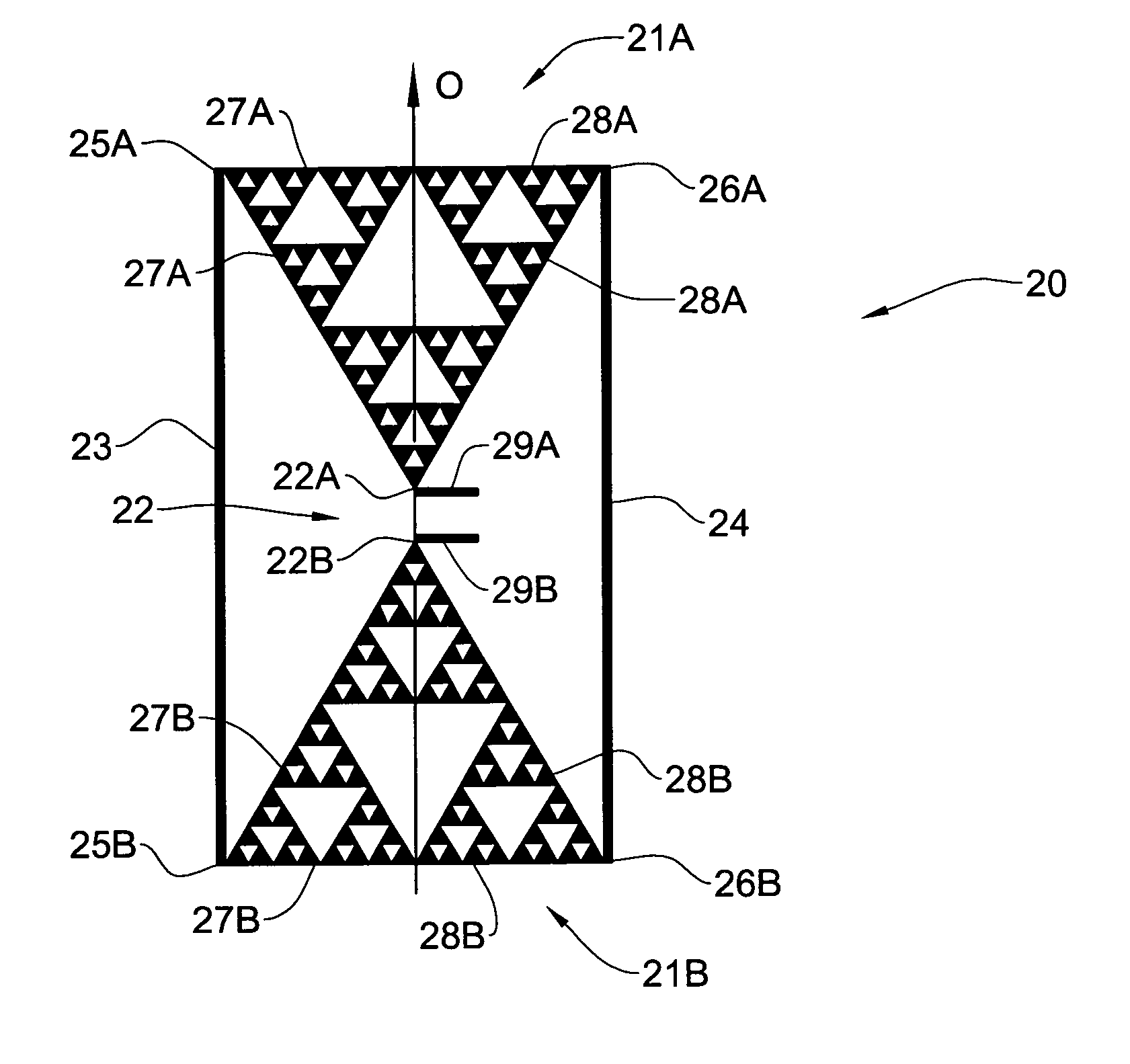
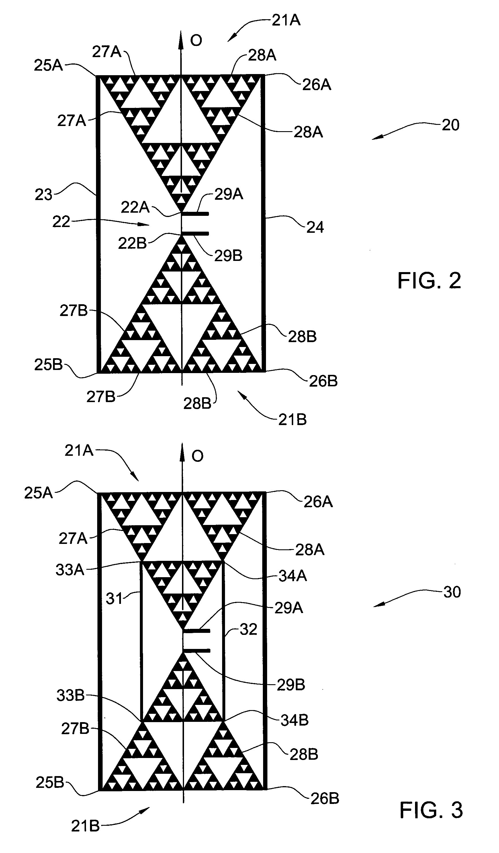
[0053] Referring now to the drawings wherein like reference numerals designate corresponding parts throughout the several views, FIG. 2 illustrate a schematic view of the fractal dipole antenna 20 according to one embodiment of the present invention. It should be noted that this figure as well as further figures (illustrating other examples of the antenna of the present invention) are not to scale, and are not in proportion, for purposes of clarity.

[0054] The fractal dipole antenna 20 includes a pair of radiating arms 21A and 21B coupled to feeding terminal 22. The feeding terminal 22 includes a pair of feeding lines 29A and 29B coupled to the radiating arms 21A and 21B, correspondingly.

[00...


PUM


Abstract

A dipole fractal antenna and a method of manufacturing thereof are described. The antenna includes a pair of oppositely directed radiating arms coupled to a feeding terminal and extended therefrom along a central axis in a common plane. At least a portion of each radiating arm has a fractal geometric shape. The antenna also includes at least one pair of electrical shunts configured for connecting at least two points selected within the fractal portion of one radiating arm correspondingly to two points selected within the fractal portion of another radiating arm. The dipole fractal antenna further may comprise a balun arranged at the feeding terminal and configured for coupling the pair of oppositely directed radiating arms to a coaxial cable to provide a balanced feed.

Description

FIELD OF THE INVENTION [0001] The present invention relates generally to antennas, and in particular, to fractal antennas. BACKGROUND OF THE INVENTION [0002] There are many applications in which the small size of the antennas is a desirable feature due to cosmetic, security, aerodynamic and other reasons. There are also applications in which surface conformability of the antennas or a possibility to mount an antenna on a platform, which is not flat or planar, is a desirable feature. [0003] For example, in mobile devices (e.g., cellular phones, PDAs, laptops, etc), reducing antenna's size is required since the amount of space available for mounting an antenna is limited. For antennas mounted on airplanes, the protrusion of the antenna beyond the surface of the plane should be minimized in order to reduce the effect of the antenna on its aerodynamic properties. [0004] Fractal antennas are known in the art as solutions to significantly reduce the antenna size, e.g., from two to four ti...

Claims


Application Information

Patent Timeline
IPC IPC(8): H01Q9/28
CPCH01Q1/36H01Q1/38H01Q1/24
Inventor ALMOG, BENYAMINHABIB, LAURENT
Owner ELTA SYST LTD
Why Eureka
Try Eureka