Ink-Jet Head and Connecting Structure

Active Publication Date: 2006-08-03
BROTHER KOGYO KK
View PDF2 Cites 21 Cited by
  • Summary
  • Abstract
  • Description
  • Claims
  • Application Information

AI Technical Summary

Benefits of technology

[0015] In the aforesaid third and fourth aspects, even when the outer edge of the flexible printed circuit is being drawn toward the energy applier or the terminal-formed member due to surface tension of the metal bond, at the time the energy applier or the terminal-formed member is connected to the flexible printed circuit with the metal bond, the flexible printed circuit does not get

Problems solved by technology

These solders may disadvantageously come

Method used


Image

  • Ink-Jet Head and Connecting Structure
  • Ink-Jet Head and Connecting Structure
  • Ink-Jet Head and Connecting Structure

Examples


Example

[0034] In the following, a preferred embodiment of the present invention will be described with reference to the accompanying drawings.

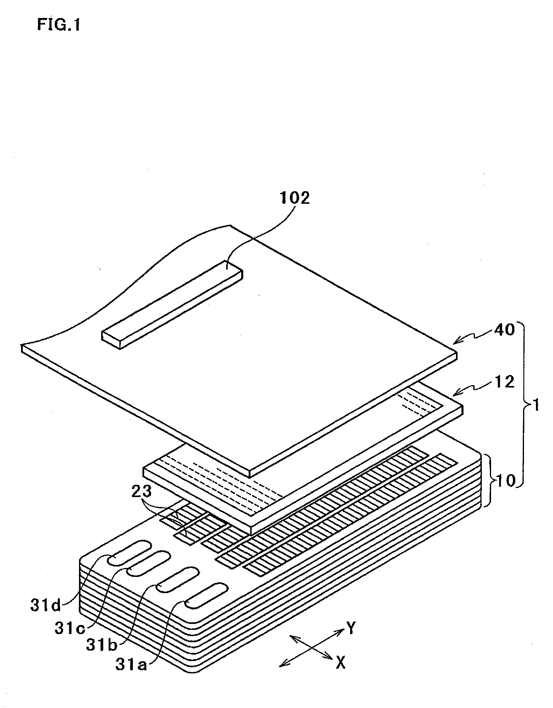
[0035] As shown in FIG. 1, an ink-jet head 1 of this embodiment includes a passage unit 10, a piezoelectric actuator 12, and an FPC 40. The head 1 is of so-called serial type, and mounted on a carriage (not illustrated) that reciprocates along a main scanning direction indicated by arrow X (hereinafter referred to as X direction) which is perpendicular to a paper conveyance direction or sub scanning direction indicated by arrow Y (hereinafter referred to as Y direction) The carriage accommodates removable ink cartridges containing cyan ink, magenta ink, yellow ink, and black ink, which are fed to the head 1.

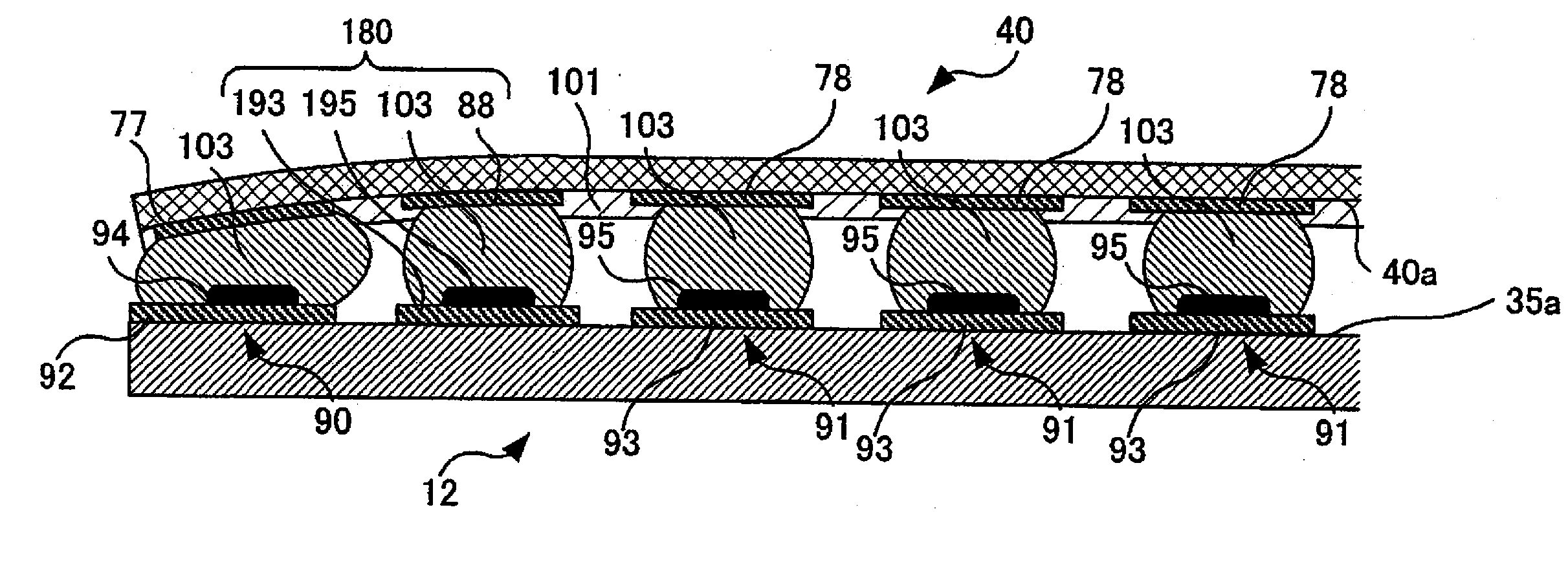
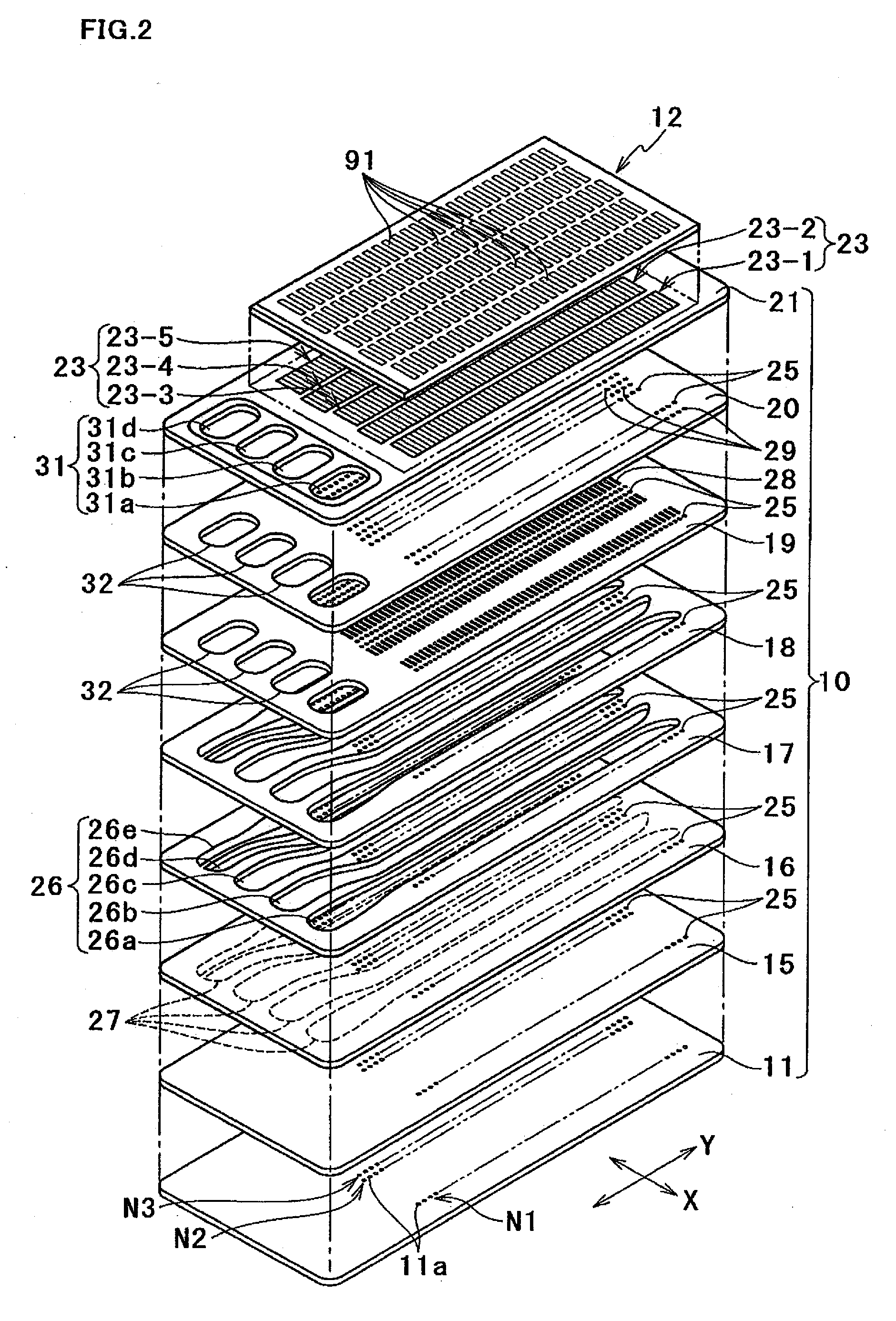
[0036] Many nozzles 11a (see FIG. 2), which open in a lower face of the passage unit, respectively communicates with the pressure chambers 23 formed in an upper face of the passage unit 10. In order to eject ink from a nozzle 11a, the piezoelect...


PUM

PropertyMeasurementUnit
Forceaaaaaaaaaa
Sizeaaaaaaaaaa
Heightaaaaaaaaaa

Abstract

An ink-jet head has a flexible printed circuit and a head main body, and further has a reinforcement that is located between drive-signal terminals arranged adjacent to one another and a constant-potential-signal terminal. The drive-signal terminals and the constant-potential-signal terminal are formed on a terminal-formed face of an energy applier included in the head main body. The flexible printed circuit has an electrode-formed face on which a constant-potential-signal electrode to be bonded to the constant-potential-signal terminal with a metal bond and drive-signal electrodes to be bonded to the drive-signal terminals with a metal bond. The reinforcement is in contact with and interposed between the terminal-formed face and the electrode-formed face so that the terminal-formed face and the electrode-formed face are spaced apart from each other.

Description

BACKGROUND OF THE INVENTION [0001] 1. Field of the Invention [0002] The present invention relates to an ink-jet head that ejects ink to a record medium, and also to a connecting structure between a flexible printed circuit and a terminal-formed member. [0003] 2. Description of Related Art [0004] Some ink-jet heads include a passage unit, an energy applier, and a flexible printed circuit (FPC). Formed in the passage unit are nozzles that eject ink and pressure chambers that respectively communicate with the nozzles. The energy applier applies ejection energy to ink in the pressure chambers. The FPC supplies a drive signal to the energy applier. Known as the energy applier is, for example, a piezoelectric actuator unit that changes the volume of the pressure chambers and thereby applies pressure as the ejection energy to ink in the pressure chambers (see Japanese Patent Unexamined Publication No. 2002-36568). [0005] The actuator unit disclosed in the aforementioned Publication include...

Claims


Application Information

Patent Timeline
IPC IPC(8): C23F1/00
CPCB41J2/14233B41J2002/14491H05K3/3452Y10T29/49401H05K2201/09781H05K2201/2009H05K3/363
Inventor KATO, YASUHIRO
Owner BROTHER KOGYO KK
Why Eureka
Try Eureka