P1 write pole with shoulder formation and method of fabrication

Inactive Publication Date: 2006-08-03
WESTERN DIGITAL TECH INC
View PDF32 Cites 2 Cited by
  • Summary
  • Abstract
  • Description
  • Claims
  • Application Information

AI Technical Summary

Benefits of technology

[0012] It is an advantage of the present invention that it produces less ATI, and thus produces fewer read/write errors.
[0013] It is another advantage of the present invention that it produces greater manufacturi

Problems solved by technology

As the areal density of storage media steadily increases and track widths become narrower and closer together, there is more and more chance of interference from adjacent tracks.
This interference naturally increases wr

Method used


Image

  • P1 write pole with shoulder formation and method of fabrication
  • P1 write pole with shoulder formation and method of fabrication
  • P1 write pole with shoulder formation and method of fabrication

Examples


Example

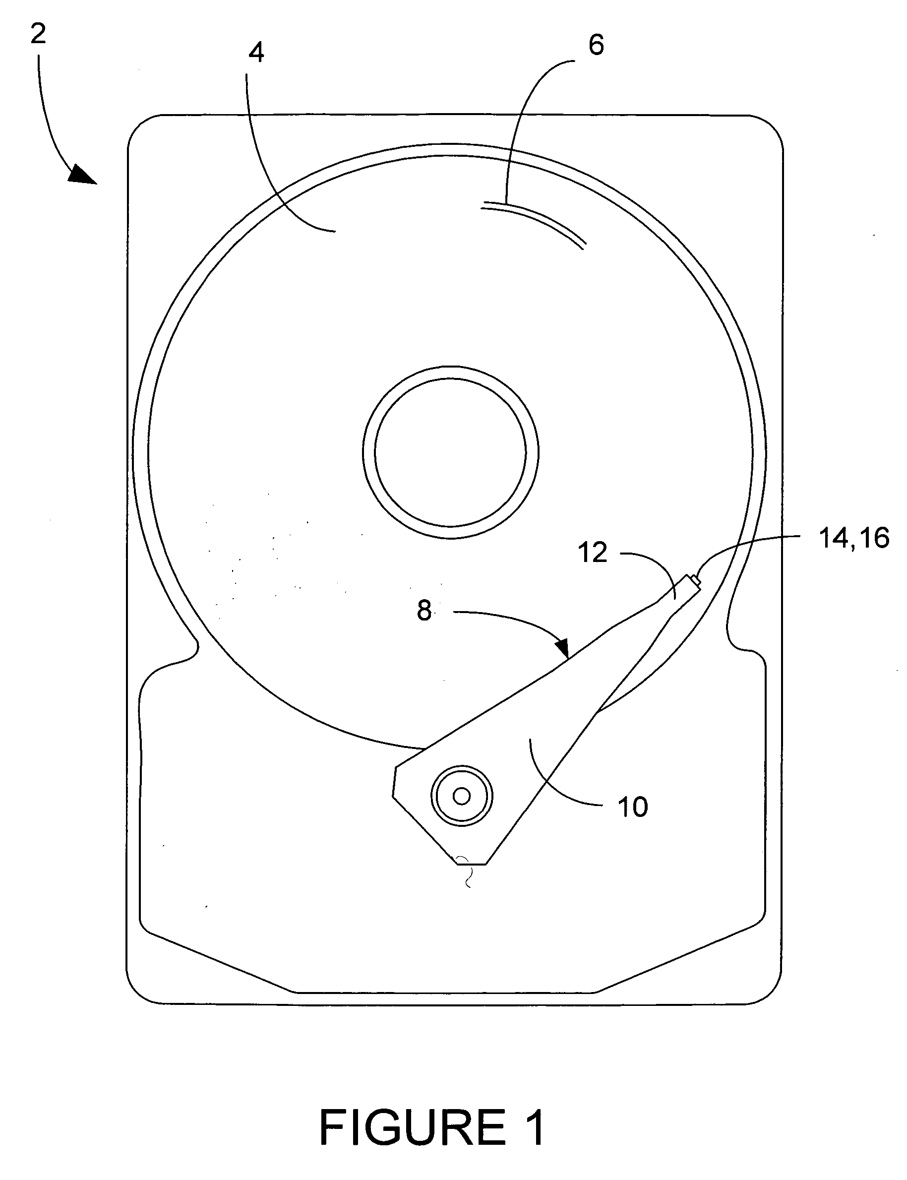
[0024] A magnetic disk drive 2 is shown generally in FIG. 1, having one or more magnetic data storage disks 4, with data tracks 6 which are written and read by a data read / write device 8. The data read / write device 8 includes an actuator arm 10, and a suspension 12 which supports one or more magnetic heads 14 included in one or more sliders 16.

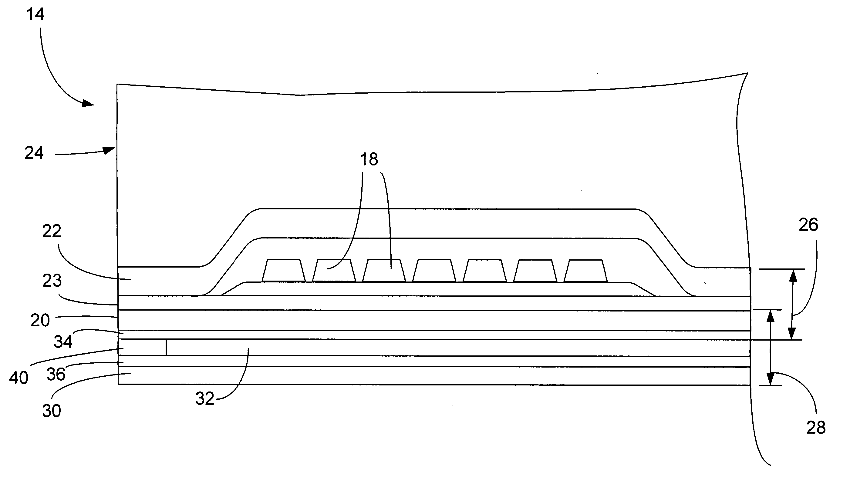
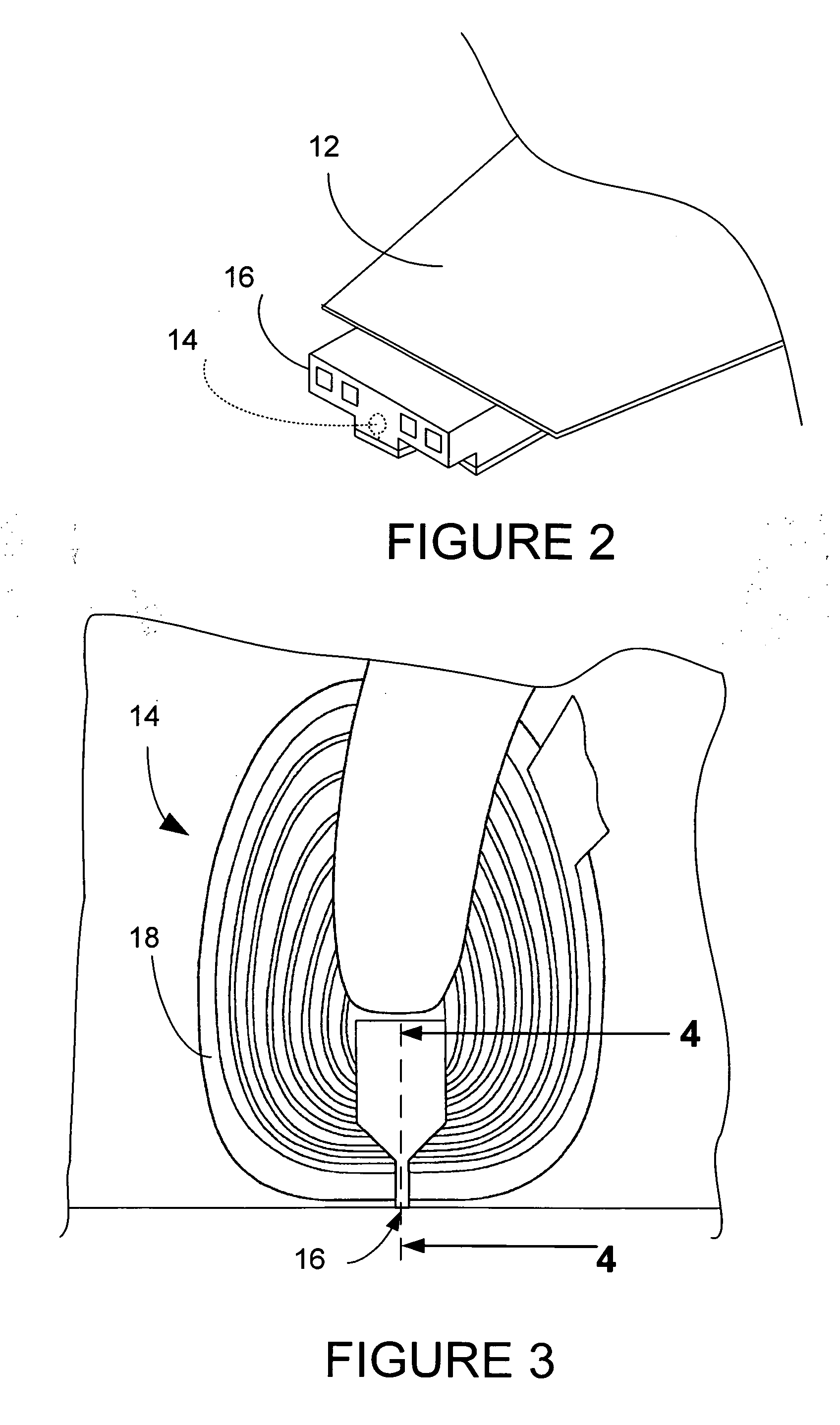
[0025]FIG. 2 shows a slider 16 in more detail being supported by suspension 12. The magnetic head 14 is shown in dashed lines, and in more detail in FIGS. 3 and 4. The magnetic head 14 includes a coil 18, P1 pole 20, and a second pole P222 which is separated from P1 pole 20 by write gap 23. The P1 pole 20, second pole P222 and write gap 23 can be considered together to be included in the write head 26.

[0026] A read sensor 40 is sandwiched between a first shield, designated as S130 and a second shield S234, and these elements together make up the read head 28. An insulation layer 32 also separates S130 and S234 in the area behind the read sen...


PUM


Abstract

A magnetic disk drive head is disclosed including a write head, which includes a P1 layer having a pedestal portion, a gap layer formed on the P1 layer, and a P2 layer formed on the gap layer. The P1 layer includes a shoulder formation having a neck portion and a beveled portion. Also disclosed is a disk drive having a write head with a P1 layer with shoulder formation, and a method for fabricating a write pole for a magnetic recording head having a P1 layer with shoulder formation.

Description

BACKGROUND OF THE INVENTION [0001] 1. Field of the Invention [0002] The present invention relates generally to manufacture of heads for data storage devices and more specifically to a write head for a hard disk drive. [0003] 2. Description of the Prior Art [0004] As the areal density of storage media steadily increases and track widths become narrower and closer together, there is more and more chance of interference from adjacent tracks. This interference has become so common that the acronym “ATI” for Adjacent Track Interference has been coined. This interference naturally increases write and read errors and is therefore undesirable. [0005] A typical read / write head 14 is shown in FIG. 4, which is a side cut-away view of the slider 16 shown in FIG. 3. The magnetic head 14 includes a coil 18, P1 pole 20, and a second pole P222 which is separated from P1 pole 20 by write gap 23. The P1 pole 20, second pole P222 and write gap 23 can be considered together to be included in the write ...

Claims


Application Information

Patent Timeline
IPC IPC(8): G11B5/147
CPCG11B5/1871G11B5/3116
Inventor BEDELL, DANIEL WAYNEGUTHRIE, HUNG-CHINJIANG, MINGLAM, HIEULO, JYH-SHUEYLEE, EDWARD HIN PONGPENTEK, ARON
Owner WESTERN DIGITAL TECH INC
Why Eureka
Try Eureka