Ultrasonic probe and ultrasonic device

a technology of ultrasonic probes and probes, applied in the field of ultrasonic probes and ultrasound equipment, can solve the problems of inconvenience in the use of probes, the difference in scanning coordinates between diagnostic ultrasound and therapeutic ultrasound, and the uninvasive treatment of the target region, so as to improve the operating ease of the ultrasound apparatus and prevent the target region.

Inactive Publication Date: 2006-08-03
HASHIMOTO ELECTRONICS IND
View PDF8 Cites 46 Cited by
  • Summary
  • Abstract
  • Description
  • Claims
  • Application Information

AI Technical Summary

Benefits of technology

[0007] According to the invention, since it is possible to so position the scanning coordinates of therapeutic ultrasounds from the therapeutic transducers and those of diagnostic ultrasounds from the diagnostic transducers as to coincide with each other, the control accuracy of the position of irradiation with the therapeutic ultrasounds can be enhanced. Also, e.g., the center of the aperture of the therapeutic transducers can be so positioned as to coincide with that of the aperture of the diagnostic transducers.
[0009] According to the invention, since it is possible to detect the progress of therapy with therapeutic ultrasounds, the operator is enabled to stop the ultrasound therapy by an alarm sounded or a warning message displayed, resulting in increased operating ease of the ultrasound apparatus. Also, the target region can be prevented from being excessively irradiated with therapeutic ultrasounds.

Problems solved by technology

Also, a target region is uninvasively treated by emitting therapeutic ultrasounds onto the subject via a therapeutic probe.
However, arranging a diagnostic probe and a therapeutic probe alongside each other on the body surface as in the conventional practice results in a difference in scanning coordinates between the diagnostic ultrasounds and the therapeutic ultrasounds according to the difference between the contact positions of the two probes.
As a result, particular care should be taken in manipulating the therapeutic probe and the diagnostic probe, inviting inconvenience in the use of probes.

Method used


Image

  • Ultrasonic probe and ultrasonic device
  • Ultrasonic probe and ultrasonic device
  • Ultrasonic probe and ultrasonic device

Examples


Embodiment Construction

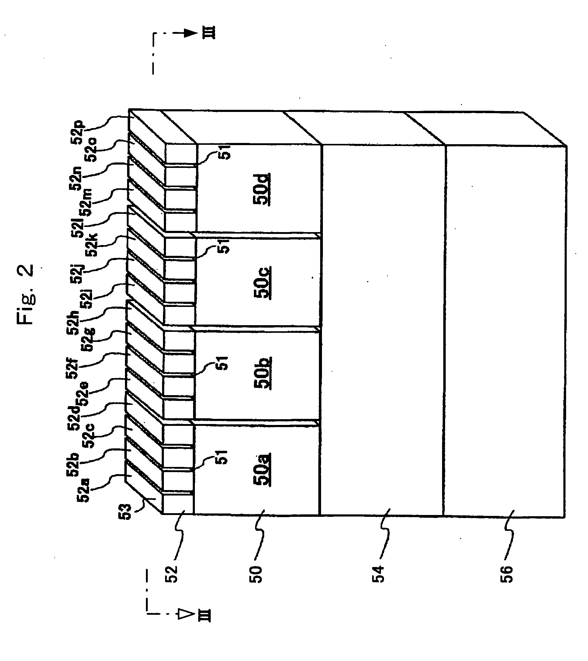
[0023] A first embodiment to which an ultrasound probe and ultrasound apparatus according to the present invention are applied will be described. This embodiment is one example of an ultrasound probe in which a plurality of diagnostic transducers are stacked over the ultrasound emitting faces of therapeutic transducers.

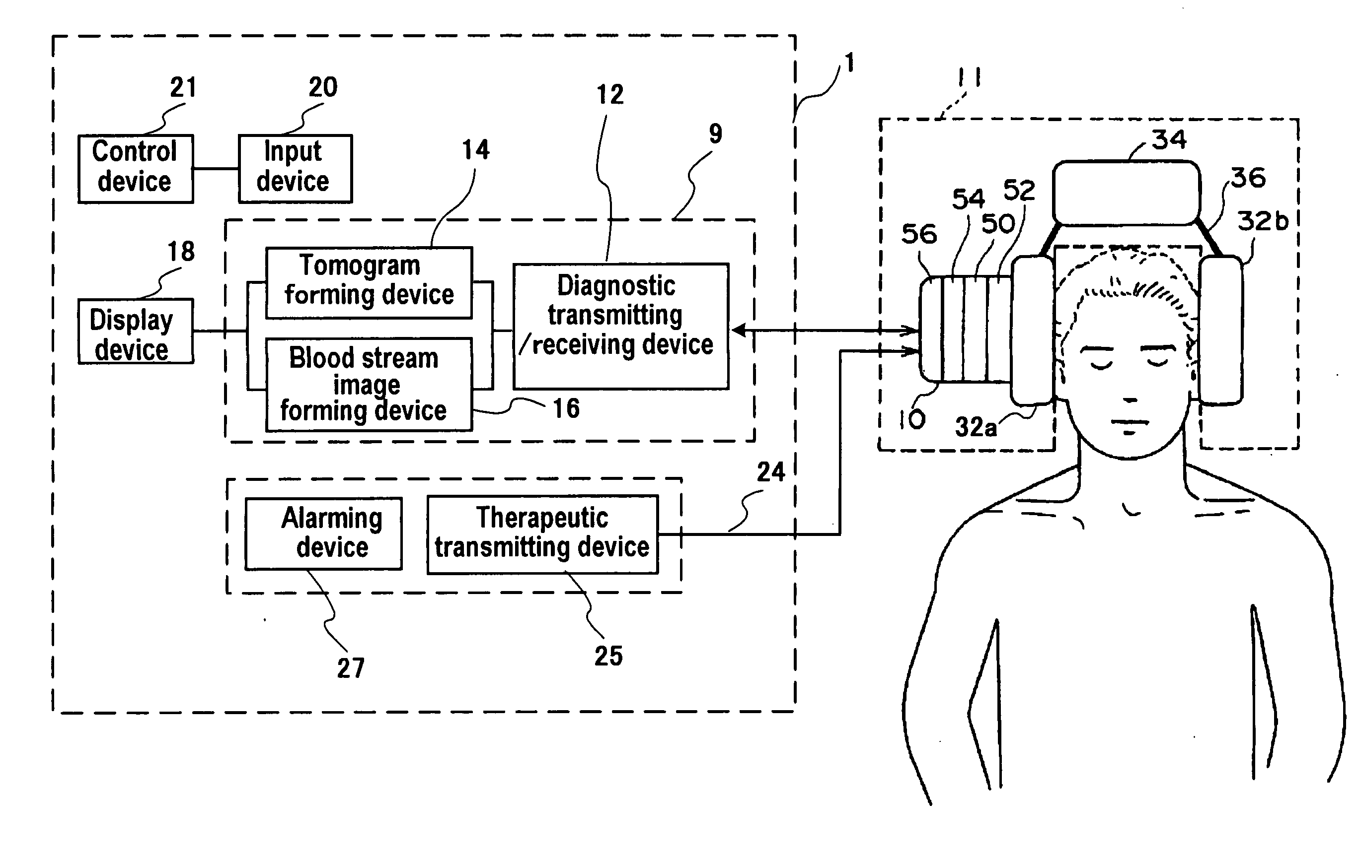
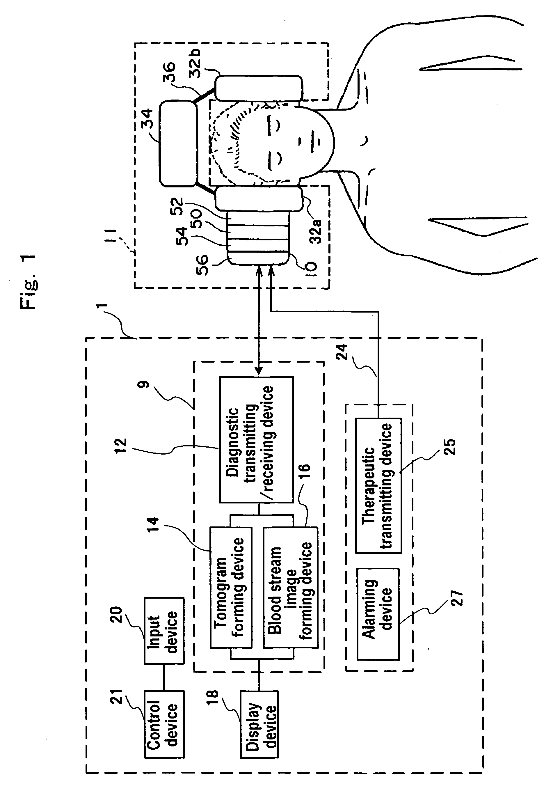
[0024] As shown in FIG. 1, an ultrasound apparatus 1 is configured of a diagnostic ultrasound unit 9, a therapeutic ultrasound transmitting unit 24, a display device 18, an input device 20, a control device 21 and so forth. The diagnostic ultrasound unit 9 is provided with a diagnostic transmitting / receiving device 12 having a diagnostic transmitting device, an image composing device including a tomogram forming device 14 and a blood stream image forming device 16, and so forth. The therapeutic ultrasound transmitting unit 24 is provided with a therapeutic transmitting device 25, an alarming device 27 and so forth. And the diagnostic transmitting / receiving device 12 ...


PUM


Abstract

An ultrasound probe comprises therapeutic transducers which include a plurality of arrayed first transducer elements and emit therapeutic ultrasounds to a subject, and diagnostic transducers which include a plurality of arrayed second transducer elements and emit diagnostic ultrasounds to the subject and receive the diagnostic ultrasounds, wherein the therapeutic transducers are stacked over the diagnostic transducers.

Description

TECHNICAL FIELD [0001] The present invention relates to an ultrasound probe and an ultrasound apparatus for use in ultrasound therapy. BACKGROUND ART [0002] In an ultrasound apparatus, therapeutic ultrasounds are emitted via a diagnostic probe kept in contact with the body surface of a subject, and ultrasound images (e.g. tomograms and M-mode images) are reconstructed on the basis of reflected echo signals generated from the subject. Also, a target region is uninvasively treated by emitting therapeutic ultrasounds onto the subject via a therapeutic probe. [0003] In performing an ultrasound therapy, a diagnostic probe and a therapeutic probe are usually arranged alongside each other on the body surface of the subject in order to emit therapeutic ultrasounds while checking the target region by its ultrasound images (see, e.g., Japanese Patent Application Laid-Open No. 5-220152). [0004] However, arranging a diagnostic probe and a therapeutic probe alongside each other on the body surfa...

Claims


Application Information

Patent Timeline
Patent Type & Authority Applications(United States)
IPC IPC(8): A61B8/12A61B8/00A61B17/22A61B19/00A61N7/00
CPCA61B8/481A61B8/546A61B17/22004A61B2019/5276A61N7/00A61B8/0816A61B2090/378
Inventor KUBOTA, JUNSASAKI, AKIRAFURUHATA, HIROSHIISHIDA, KAZUNARIUMEMURA, SHINICHIROAZUMA, TAKASHIASAFUSA, KATSUNORI
Owner HASHIMOTO ELECTRONICS IND
Why Eureka
Try Eureka