Pen-holding posture corrective apparatus

a technology of corrective apparatus and pen, which is applied in the field of pen-holding posture corrective apparatus, can solve the problems of index finger bending, deformation, tilting and deformation, and parents rarely pay much attention to the fundamental learning process

Inactive Publication Date: 2006-08-10
YOU MONG CHIEN
View PDF12 Cites 18 Cited by
  • Summary
  • Abstract
  • Description
  • Claims
  • Application Information

AI Technical Summary

Benefits of technology

[0017] In view of the foregoing, an object of the invention is to provide a pen-holding posture corrective apparatus to enable a user to learn how to correctly hold a pen for writing without suffering from fatigue and possible injury due to improper pen-holding posture.

Problems solved by technology

Furthermore, the shaft of the writing tool is thin and round, the user tends to grip the shaft with greate strength to prevent the shaft from slipping backwards during use, resulting bending, tilting and deformation of the index finger.
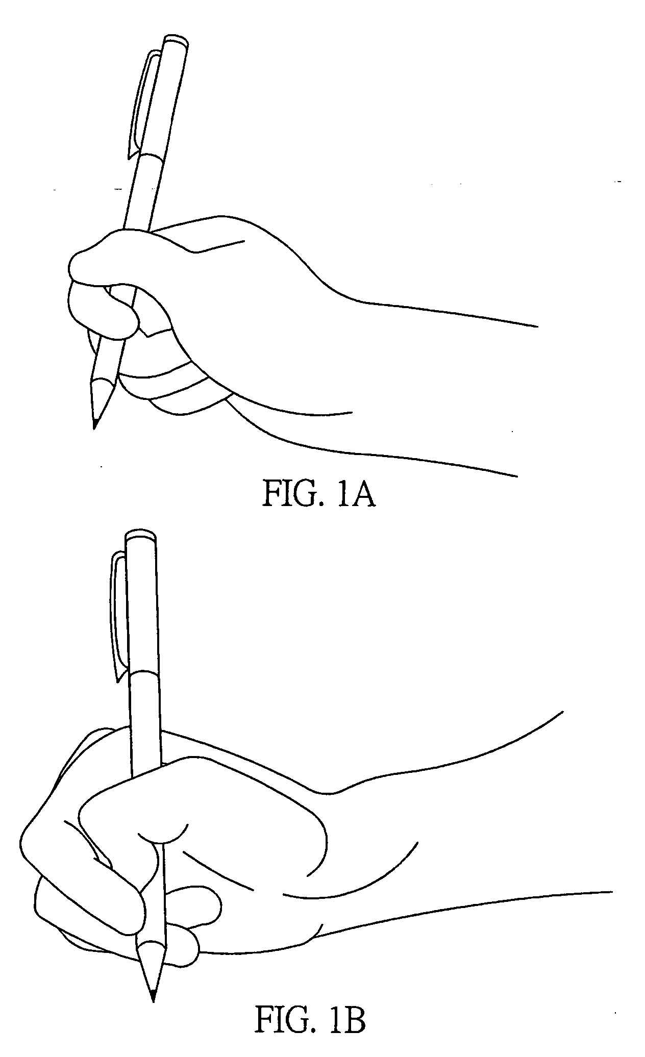
However, parents seldom pay much attention to fundamental learning process, causing many to adapt to incorrect pen-holding posture and writing habits since their young age.
As a result, any incorrect pen-holding habit easily puts pressure on a user, particularly a child, and makes the user feeling discomfortable, as well as fatigue in bone and muscle, and even injury.
Furthermore, an improper pen-holing posture may result a learning barrier for a child who feels a strong antipathy towards writing and learning.
However, neither the user can correct his / her incorrect pen-holding posture nor can the user feel relaxed and comfortable by using the pen-holding trainer 10.
Therefore, the user's index finger may easily get deformed under pressure.
Thus, the pen-holding trainer 10 does not provide a proper pen-holding tool for a child, as the child gets tired of holding the pen and dislike writing even more when using the pen-holding trainer 10.
However, due to different finger and joint sizes of different users user's fingers and joints may get stuck inside the insertion tubes 22 and 23, which are too small when the fingers are inserted and removed from the insertion tubes 22 and 23.
Moreover, if the insertion tubes 22 and 23 are too large compared to the user's finger sizes, not only are the insertion tubes difficult to grip, but the fingers also can not be positioned with certainty in the insertion tubes 22 and 23, making it difficult to do any writting.
Therefore, other fingers are not positioned to maintain the correct pen-holding posture of “griping firmly by fingers with the palm unoccupied”.
Therefore, when the auxiliary pen-holding trainer 20 is used, a user has to hold the palm tightly with fingers, leading to overtension for the finger joints and energy wasting postures where the shaft is held by the user's fingertips.
As a result, the user cannot loosen up his / her finger muscles and bones and easily gets muscles fatigue.
However, the pen-holding trainer 30 merely enables the thumb, the index finger and the middle finger to be positioned, but muscles and bones of the ring finger and little finger are not be kept in correct postures, respectively.
Therefore, the pen-holding trainer does not completely solve conventional problems discussed above.
Moreover, the prior arts discussed above do not remind the user when the pen is held in an incorrect posture.
And if the user does not hold the pen according to a correct posture, the locations for positioning the fingers still do not help to improve user's incorrect pen-holding postures, such as wrong manipulation of the fingers, exertion of excessive force, and so.
As a result, the user is still unfamiliar with the correct pen-holding posture.

Method used


Image

  • Pen-holding posture corrective apparatus
  • Pen-holding posture corrective apparatus
  • Pen-holding posture corrective apparatus

Examples


embodiment 1

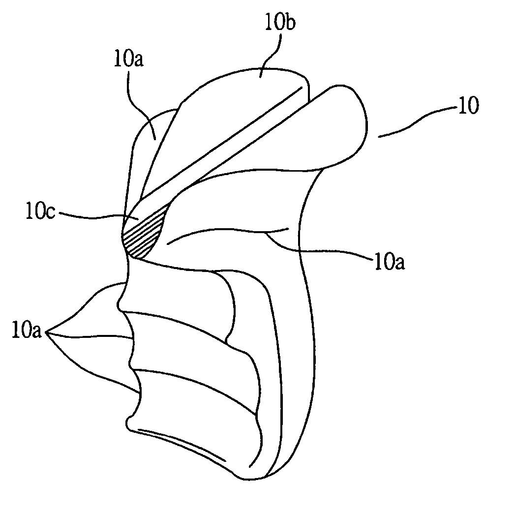
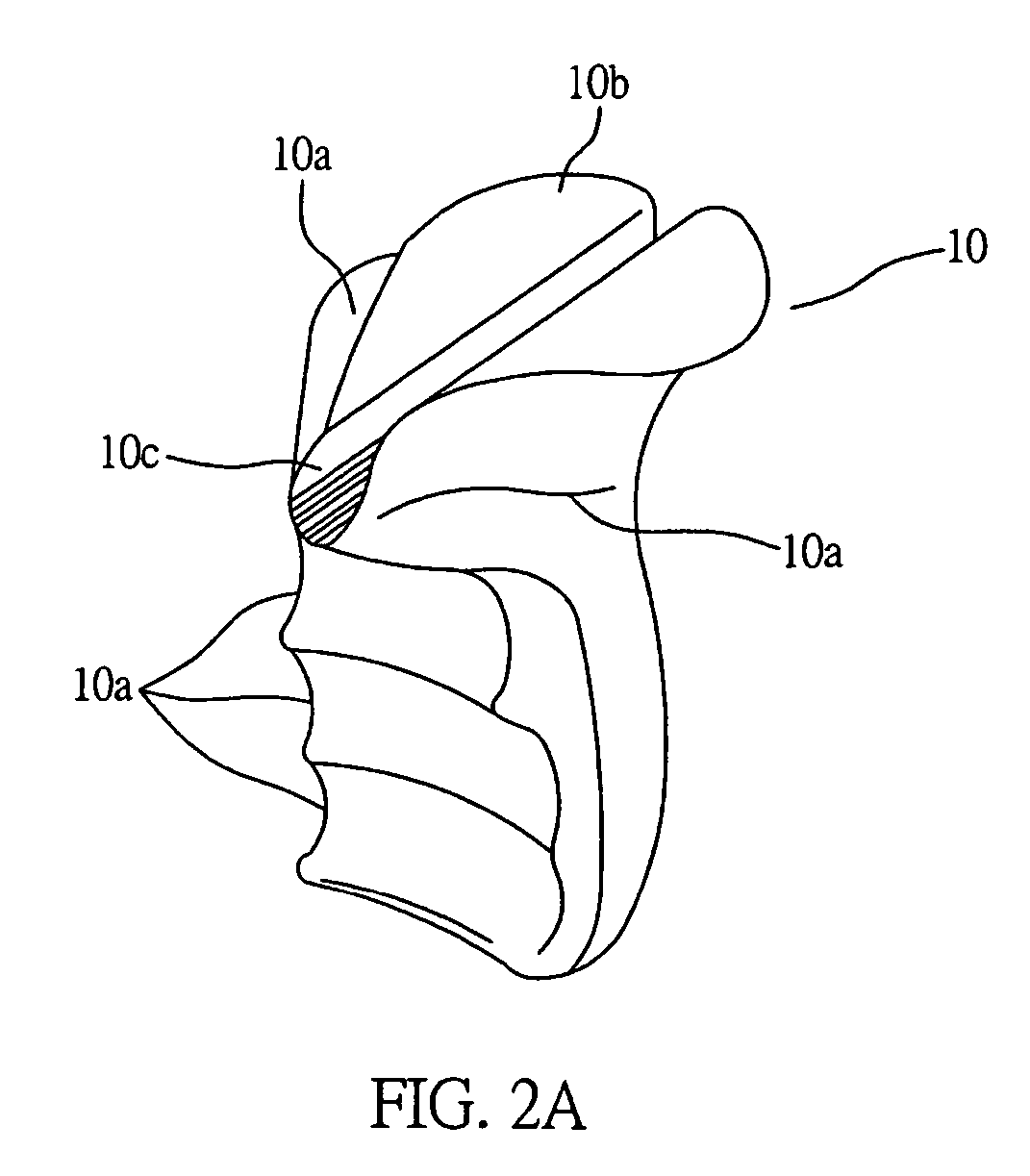
[0042] FIGS. 5 through to 7 are schematic diagrams illustrating the pen-holding posture corrective apparatus 1 according to the first embodiment of the invention. As shown in the diagrams, the pen-holding posture corrective apparatus 1 comprises a main body 11, a supporting part 12, a first poisitioning part 13, a second poisitioning part 14, a third poisitioning part 15, a fourth poisitioning part 16, and a pen-holding part 17. The present embodiment of the invention is described with the user holding a writing tool 100 by his / her right hand as an example to apply the present invention, and only the posture corrective apparatus applicable to right hand holding the writing tool 100 is illustrated. However, it should be understood that the pen-holding posture corrective apparatus of the invention is also applicable to left-handed users as long as the pen-holding posture corrective apparatus 1 is designed correspondingly to suit the left hand holding the writing tool 100. The pen-hold...

embodiment 2

[0053] FIGS. 8 through to 10 are schematic diagrams illustrating a pen-holding posture corrective apparatus 1′ according to the second embodiment of the invention. As shown in the diagrams, the pen-holding posture corrective apparatus 1′ is mounted on a forepart 100a′ of a writing tool 100′. The pen-holding posture corrective apparatus 1′ comprises a first poisitioning part 11′, a second poisitioning part 13′, a third poisitioning part 15′ and a plurality of sensor components 17′. The pen-holding posture corrective apparatus 1′ has the similar function to the pen-holding posture corrective apparatus 1 illustrated in the first embodiment, so the similar functions will not be described further. The description in the second embodiment only focuses on structures and functions different from the first embodiment to provide a better understanding of the features and advantages of the invention.

[0054] As shown in FIGS. 8 and 9, the first poisitioning part 11′ is formed on a side of the f...


PUM


Abstract

A pen-holding corrective apparatus is formed with at least a plurality of poisitioning parts for positioning the thumb, the middle finger and the index finger of a user, so as to combine points of force exertion for the thumb, the middle finger and the index finger via the positioning parts and enable the ring finger and the little finger to curl behind the middle finger, so that the user can master a correct pen-holding posture with the pen-holding corrective-apparatus, whereby the user's fingers can curl naturally without touching the palm when the user holds a writing tool.

Description

BACKGROUND OF THE INVENTION [0001] 1) Field of the Invention [0002] The invention relates to a pen-holding posture corrective apparatus, in particular, to an apparatus that enables a user to learn how to correctly hold a pen for writing without suffering from fatigue and possible injury due to improper pen-holding posture. [0003] 2) Description of the Prior Art [0004] Typically, a conventional writing tool, such as a ball-point pen, pencil, fountain pen, marker, dip-pen, artist's pen, or mapmaker's pen has a cylindrical shaft with very small arc. So, when a user holds the pen too tightly for a long time, a deep-groove mark is left on the distal joint (the joint that is farthest from the palm) of the middle finger, or even calluses formed on the middle finger and / or the thumb. Furthermore, the shaft of the writing tool is thin and round, the user tends to grip the shaft with greate strength to prevent the shaft from slipping backwards during use, resulting bending, tilting and deform...

Claims


Application Information

Patent Timeline
Patent Type & Authority Applications(United States)
IPC IPC(8): B25G1/10
CPCB43K23/008Y10T16/476G09B11/02
Inventor YOU, MONG-CHIEN
Owner YOU MONG CHIEN
Why Eureka
Try Eureka