Assembly for creating milk froth and/or for heating milk

a technology for heating milk and milk froth, which is applied in the direction of milk treatment, application, paints with biocides, etc., can solve the problems of complex and therefore expensive application of teflon® coatings on non-planar surfaces, serious health risks, and complicated application of such microbicidal coatings, so as to achieve easy cleaning and less subject to contamination

Inactive Publication Date: 2006-08-10
KONINKLIJKE PHILIPS ELECTRONICS NV
View PDF9 Cites 6 Cited by
  • Summary
  • Abstract
  • Description
  • Claims
  • Application Information

AI Technical Summary

Benefits of technology

[0009] It is an object of the present invention to provide an assembly for creating milk fro

Problems solved by technology

A disadvantage of such an assembly may be seen in the fact that it is quickly contaminated, that it is not microbicidal, and that the milk residues remaining in the foaming device after each foaming operation are subject to the influence of bacteriae, leading to a serious health risk.
A disadvantage of suc

Method used


Image

  • Assembly for creating milk froth and/or for heating milk
  • Assembly for creating milk froth and/or for heating milk
  • Assembly for creating milk froth and/or for heating milk

Examples


Embodiment Construction

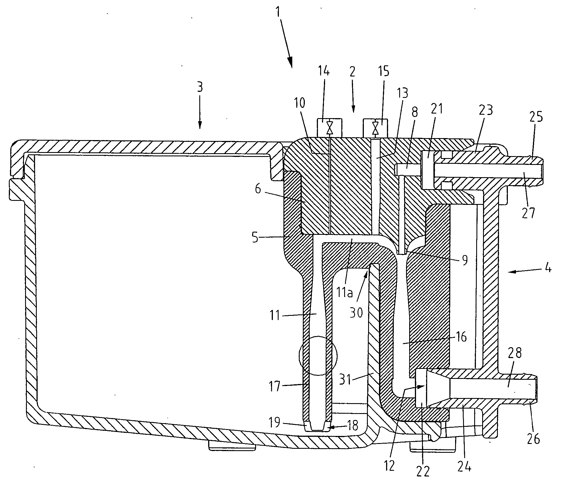
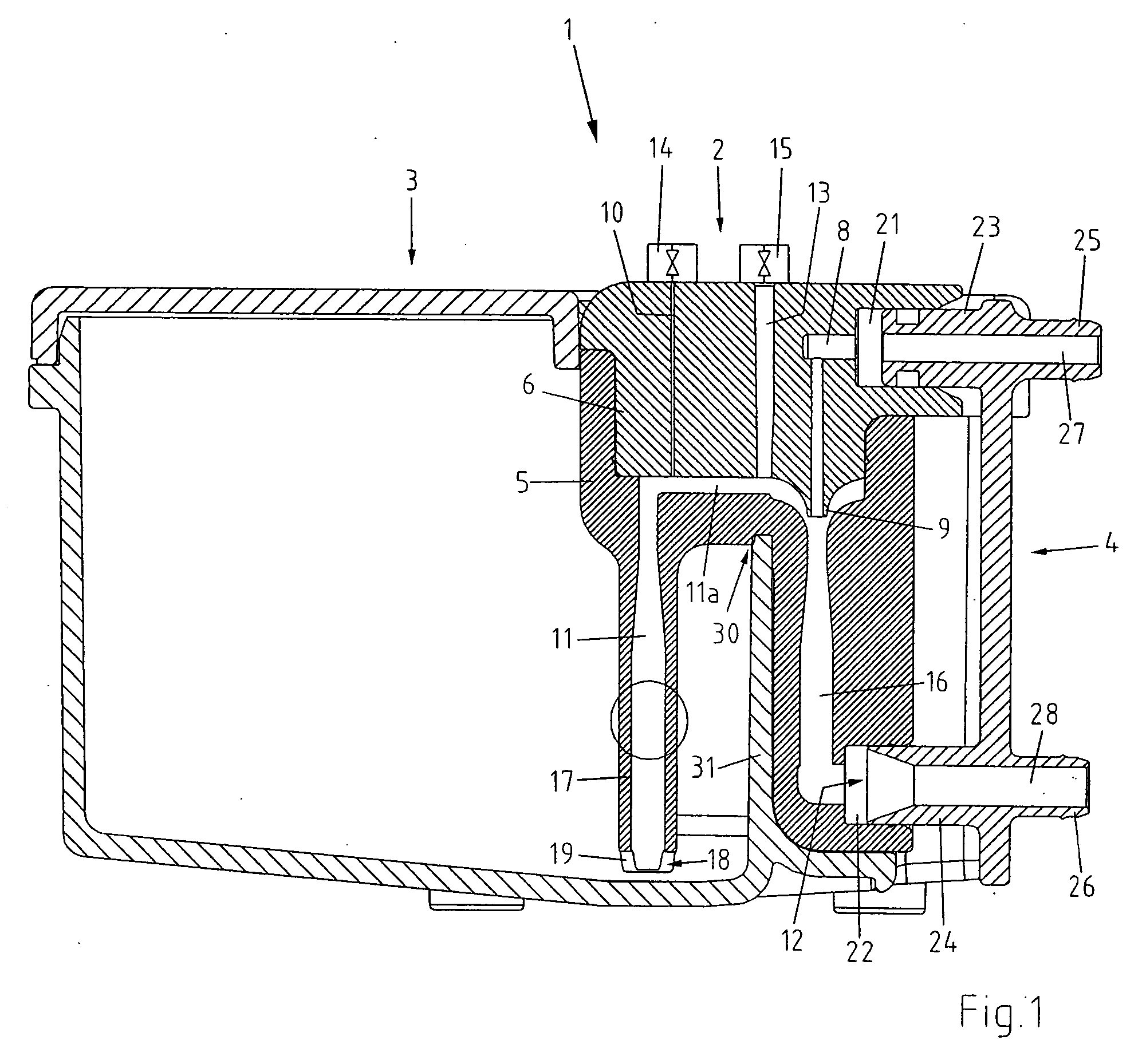
[0019] The assembly for creating milk froth and for heating milk is designated, as a whole, by reference numeral 1. Essentially, the assembly 1 comprises a foaming device 2, a milk container 3, and a coupling element 4. The foaming device 2 comprises a lower portion 5 and an upper portion 6, attached to each other by means of a push-fit connection. The lower portion 5 is sealingly attached to the upper portion 6, whereby the required sealing gaskets are not shown in this view of the drawing. The foaming device 2 comprises a steam supply channel 8, an air supply channel 10, a milk supply channel 11, a discharge opening 12 as well as a venting channel 13. The horizontally extending portion of the milk supply channel 11 is designated by reference numeral 11a. The end of the steam supply channel 8 is designed as a nozzle 9.

[0020] Both the air supply channel 10 and the venting channel 13 each are provided with a valve member 14, 15 by means of which the channels 10, 13 can be selectivel...


PUM

PropertyMeasurementUnit
Bondaaaaaaaaaa

Abstract

An assembly for creating milk froth and/or for heating milk is disclosed. It comprises a foaming device and optionally a milk container and a valve assembly. The foaming device is provided with a steam supply channel, an air supply channel, a milk supply channel and a discharge opening. In order to provide for an easy cleaning of the assembly and its microbicity, at least the components and/or cavities coming into contact with milk are provided with a hydrophobic and oleophobic surface consisting of nano-particles which consist partially of silver or a silver compounds.

Description

BACKGROUND OF THE INVENTION [0001] The present invention refers to an assembly for creating milk froth and / or for heating milk, comprising a foaming device including a steam supply channel, an air supply channel, a milk supply channel, and a discharge opening. For the sake of simplicity, such assemblies are called hereafter also as “frothers” or “milk frothers”. [0002] For creating milk froth, so-called milk foaming devices or emulsifying devices are known in various embodiments. Usually, these milk foaming devices or emulsifying devices comprise a steam supply channel, opening into a suction chamber. The suction chamber communicates with a milk supply channel and an air supply channel. By means of the steam flow, a negative pressure is created in the suction chamber, said negative pressure causes milk to flow via the milk supply channel into the suction chamber and air to flow via the air supply channel into the suction chamber. The so created mixture of steam, air and milk is brou...

Claims


Application Information

Patent Timeline
IPC IPC(8): A23C1/00
CPCA47J31/4485A47J36/02B01F5/0413B01F5/0428C09D5/14C09D5/1618B01F25/31242B01F25/312A47J31/36A47J31/40A47J31/4489
Inventor FRIGERI, PATRIZIO
Owner KONINKLIJKE PHILIPS ELECTRONICS NV
Why Eureka
Try Eureka