Optical elements having gradient optical properties

a technology of optical properties and optical elements, applied in the field of optical elements having gradient optical properties, can solve the problems of difficult control of the distribution of gradient optical properties within the substrate, limited size of optical elements, etc., and achieve the effects of reducing manufacturing time and cost, improving light transmission, and cost saving

Active Publication Date: 2020-09-24
MOMENTUM OPTICS LLC
View PDF0 Cites 2 Cited by
  • Summary
  • Abstract
  • Description
  • Claims
  • Application Information

AI Technical Summary

Benefits of technology

[0009]With the disclosed method, a multiplicity of GOPOEs may be fabricated at once thereby reducing manufacturing time and costs compared to traditional mechanical processing of individual optical elements. Furthermore, depositing films on batches of optical elements would likewise result in a cost savings. A substrate of GOPOEs may collectively receive prescribed coatings to prevent light reflection (i.e. anti-reflection coatings) or to filter color or infrared light. Moreover, a substrate of optical elements may be coated in a light blocking film and openings formed in said film using standard semiconductor processing techniques so as to create apertures over the GOPOEs.
[0010]A GOPOE may be removed from the substrate using dicing, dry etching, wet etching or a combination thereof. An individual GOPOE released from the substrate is herein referred to as an “optical element chip”. Optical element chips may be used as individual components, abutted together to form optical systems or combined with conventional homogenous optical elements. Using dry and / or wet etching to remove the GOPOEs from the substrate enables an optical element chip to have any desired shape; for example, a chip may be rectangular or circular. Planar optical elements that are abutted to form optical systems exhibit minimal tilt error, less light reflection from air-to-substrate interfaces thus improving light transmission and have fewer exposed surfaces making them less prone to contamination.
[0011]In some embodiments, alignment marks are created using photolithography and etching to pattern a substrate containing multiple GOPOEs. Two or more of these substrates are aligned to each other using the alignment marks and then bonded to each other, thereby forming optical systems. The bonded substrates are diced to release the stacked optical element chips. Stacking the chips on a substrate-level simplifies assembly and provides tighter assembly tolerances than mechanically aligned and assembled optical elements.

Problems solved by technology

While the cost of manufacturing micro optical elements (e.g. micro lens arrays) with gradient properties on a substrate is relatively inexpensive, these optical elements are limited to small sizes and the distribution of gradient optical properties within the substrate is not easily controlled.

Method used


Image

  • Optical elements having gradient optical properties
  • Optical elements having gradient optical properties
  • Optical elements having gradient optical properties

Examples


example

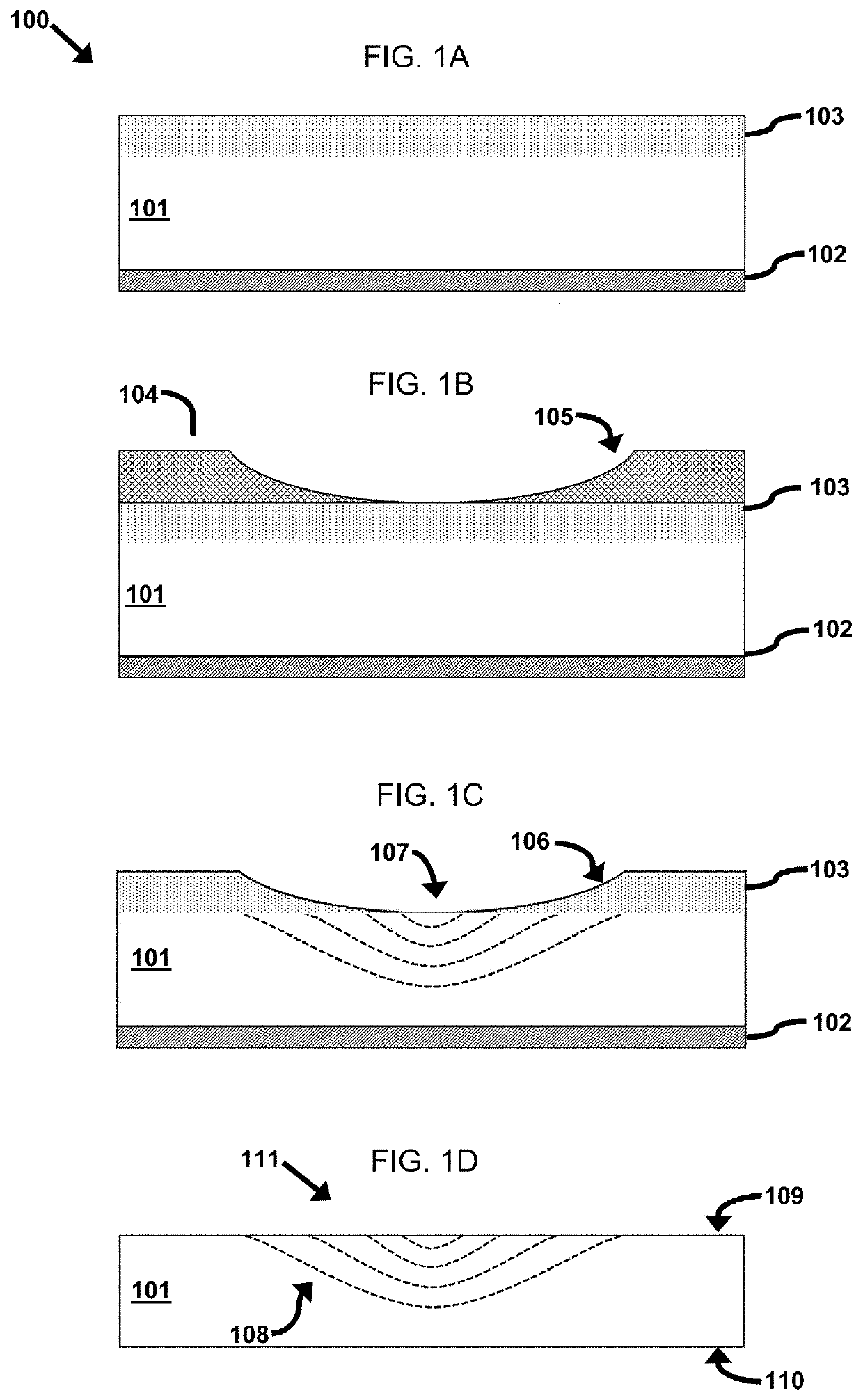
[0047]A glass article having desired mechanical and optical properties is selected for use as a substrate. The substrate has a sodium content greater than 5 mol % and less than 30 mol %. The thickness of the substrate may be 0.1-5 mm. The top and bottom surfaces of the substrate are polished. An ion diffusion preventing barrier material such as Silicon Nitride is disposed on the bottom surface of the substrate using chemical vapor deposition. The substrate is placed in a KNO3 salt solution at an elevated temperature below the glass transition temperature of the substrate. Potassium ions are exchanged for Sodium ions within 1-100 μm of the top surface of the substrate. Potassium ions decrease the diffusivity at the surface of the glass substrate thereby creating a DRM in the top surface of the substrate. The DRM is coated in photoresist. The photoresist is patterned using grayscale photolithography and a developer solution to create a three-dimensional surface relief patterns in the ...


PUM

PropertyMeasurementUnit
thickaaaaaaaaaa
thickaaaaaaaaaa
diameteraaaaaaaaaa

Abstract

A method for creating gradient optical properties within a substrate is disclosed herein. More specifically, the present invention teaches a method whereby a material disposed on a substrate is patterned in three dimensions such that the thickness and diffusivity properties of the material can be used to regulate the diffusion of ions into the substrate. An example is given in which ions, injected into a substrate through an ion exchange process, alter the refractive index within the substrate in a pre-selected fashion to form a gradient refractive index lens.

Description

BACKGROUND[0001]The present disclosure relates generally to optical elements having gradient optical properties and particularly to providing gradient optical properties to optical elements using micro fabrication processes.[0002]Traditional optical elements, such as lenses and prisms, are manufactured from materials with homogenous material properties. The index of refraction, for example, is constant throughout the entire optical element. However, for some time, those skilled in the art of optical system design have known that an optical element having material properties that spatially vary in a selected fashion can enhance the performance of the optical system. One such optical element is a gradient refractive index (GRIN) lens wherein the refractive index varies spatially within the lens. An advantage of using GRIN lenses in an optical system is that the system may exhibit less monochromatic aberration than a system constructed from traditional lenses.[0003]Most gradient optica...

Claims


Application Information

Patent Timeline
Patent Type & Authority Applications(United States)
IPC IPC(8): G02B3/00G02B1/12C03B23/22
CPCG02B3/0087C03B23/22G02B1/12C03C21/002C03C17/225
Inventor GOECKERITZ, JEREMY
Owner MOMENTUM OPTICS LLC
Why Eureka
Try Eureka