
Side RF coil and side heater for plasma processing apparatus

a plasma processing and side heater technology, applied in applications, agriculture, coatings, etc., can solve the problems of dome fracture, lack of repeatability of deposited film, and fluctuation in the quality of the process on the wafer

Inactive Publication Date: 2006-08-10
APPLIED MATERIALS INC
View PDF6 Cites 22 Cited by
  • Summary
  • Abstract
  • Description
  • Claims
  • Application Information

AI Technical Summary

Benefits of technology

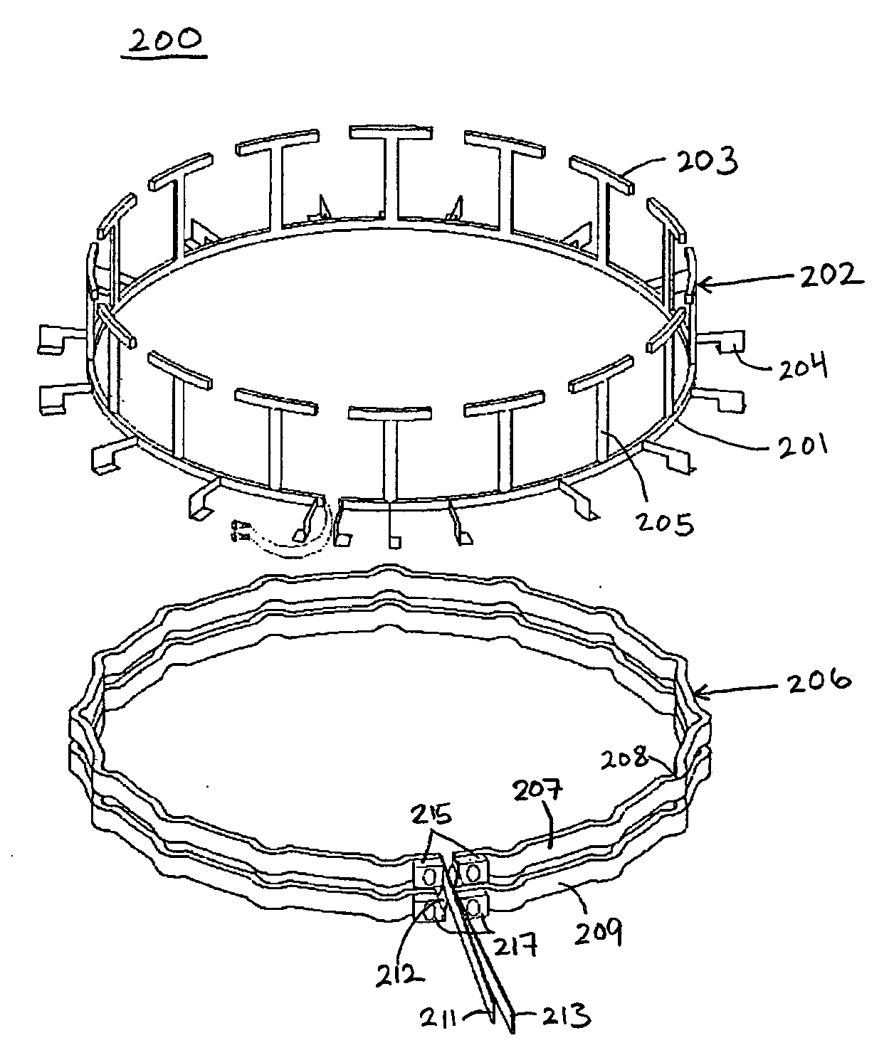
[0011] Embodiments of the invention further include a method of controlling a temperature of a plasma chamber. The method may include the step of disposing, adjacent to a chamber sidewall, a heater that includes an elongated first heating element substantially parallel to an elongated second heating element. The first and second heating elements may be joined by one or more posts substantially perpendicular to the heating elements. The method also includes the step of disposing a cooling element adjacent to the chamber sidewall between the first heating element and the second heating element. The cooling element may include a crease at points of overlap with the posts, such that the cooling element and the first and second heating elements avoid physical contact and maximize thermal interaction with the chamber.

Problems solved by technology

One factor affecting the quality of the process on the wafer is fluctuation in dome temperature.
Fluctuation in dome temperature may generate particles that deposit on the wafer and cause a lack of repeatability of a deposited film of material.
In addition, variation in temperature over regions of the dome may result in excessive thermal stress that can ultimately result in dome fracture.
Another issue faced by the designers of plasma generation chambers is capacitive coupling between the RF coil and the ions of the plasma.
High ion energies give rise to excessive ion bombardment on the dome wall adjacent to the RF coil, thereby increasing the number of contaminant particles and the temperature of the ceramic dome.

Method used


Image

  • Side RF coil and side heater for plasma processing apparatus
  • Side RF coil and side heater for plasma processing apparatus
  • Side RF coil and side heater for plasma processing apparatus

Examples


Embodiment Construction

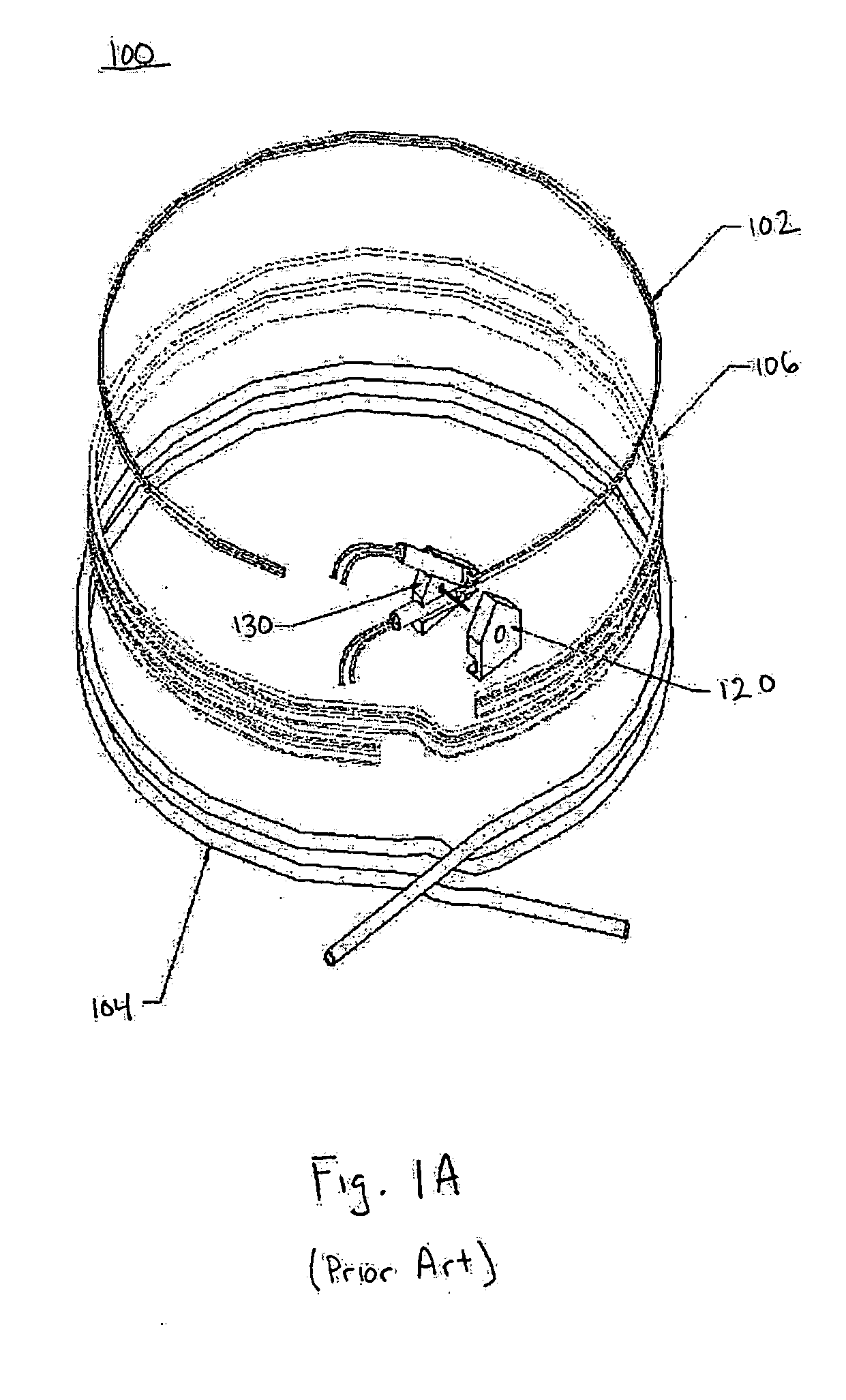
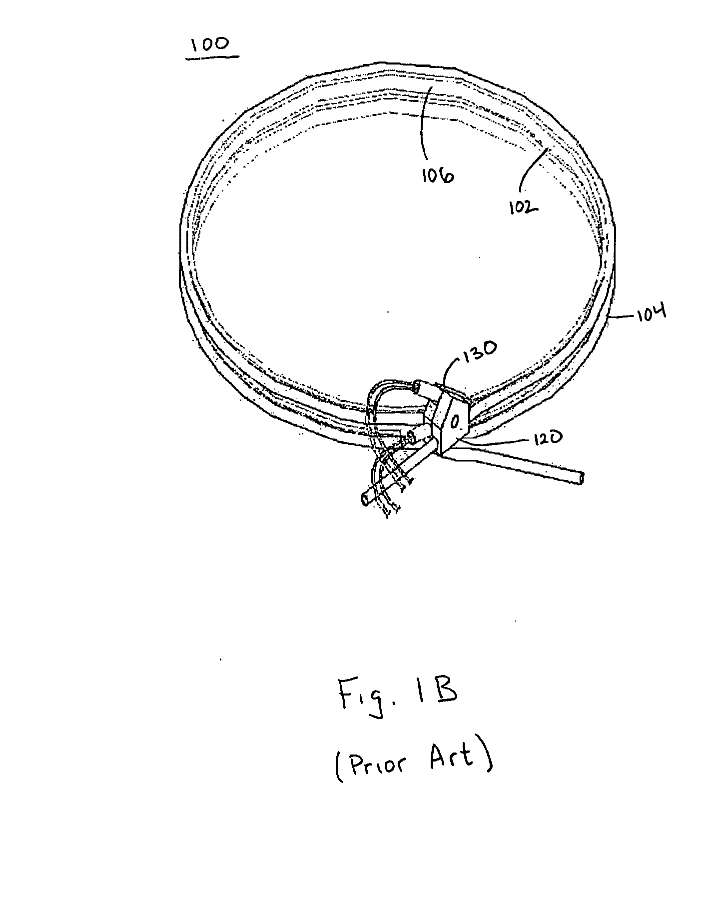
[0026]FIGS. 1A and 1B show expanded and assembled views of a conventional side RF coil and heater assembly 100. The assembly has heater 102 and RF coil 104 concentrically aligned and coupled by frame 106. The heater 102, RF coil 104 and frame 106 may also be coupled by interconnect 120 and assembly 130.

[0027]FIG. 1C shows a plan view of the conventional side RF coil and heater assembly 100. This view shows the concentric and coplanar alignment of the heater 102 and RF coil 104. The RF coil 104 may be held in position relative to the heater 102 by frame 106, which has tabs 108 that extend out and support the windings of the RF coil 104. The assembly 100 may be positioned around the outside of a dome sidewall (not shown) that helps defines the plasma generation space of a plasma chamber. In this configuration, the heater 102 is positioned closer to the dome sidewall than RF coil 104. The heater 102 will also be cooled with the dome sidewall when RF coil 104 circulates cooling fluid t...


PUM

PropertyMeasurementUnit
Temperatureaaaaaaaaaa
Poweraaaaaaaaaa
Densityaaaaaaaaaa

Abstract

A RF plasma generation and temperature control system for an inductively coupled plasma process chamber. The plasma generation system includes a heater that includes an elongated upper heating element substantially parallel to an elongated lower heating element, where the upper and lower heating elements are joined by one or more posts substantially perpendicular to the upper and lower heating elements. The system also including one or more RF coils featuring a crease at points of overlap with the posts. Also, a RF plasma generation system for an inductively coupled plasma process chamber, where the plasma generation system includes a heater thermally coupled to the chamber, and one or more RF coils coupled to the chamber, where the RF coils include a hollow tube having at least one flat side.

Description

BACKGROUND OF THE INVENTION [0001] Several methods for fabricating semiconductor devices utilize a plasma generated or maintained within a processing chamber. The character of the plasma within the chamber has an important effect upon the results of the fabrication process, such as etching or chemical vapor deposition. [0002] For example, the quality of the plasma generated may be characterized by uniformity, plasma potential, and electron temperature among other characteristics. One kind of plasma reactor of interest is the inductively coupled plasma reactor. The plasma in such a reactor is generated inside a vacuum chamber by RF coils (also referred to as antenna), typically located on the top of the dome and / or around the outer side wall of the dome. [0003] By adjusting the RF current in the coil, the density of the ions can be controlled. The energy of the ions can be controlled by another RF power, usually called RF bias, that is connected to the wafer pedestal. However, ion en...

Claims


Application Information

Patent Timeline
IPC IPC(8): C23C16/00C23F1/00H01L21/306
CPCC23C16/46C23C16/507H01J37/321H01J37/32174H01L21/67069H01L21/67109
Inventor LONG, MAOLINSUN, DAVID P.
Owner APPLIED MATERIALS INC
Learn More