Product diverter and method

a diverter and product technology, applied in the direction of transportation and packaging, conveyor parts, packaging, etc., can solve the problems of inability to produce packaging formats that require more products in width, limited wrappers, and equipment installation and maintenance costs, and achieve the effect of less width

Inactive Publication Date: 2006-08-10
PAPER CONVERTING MASCH CO INC
View PDF8 Cites 27 Cited by
  • Summary
  • Abstract
  • Description
  • Claims
  • Application Information

AI Technical Summary

Benefits of technology

[0013] A second object of the present invention is to offer an alternative method that maintains the ability to produce package formats that are lesser in width than the number of lanes of product being delivered at the wrapper infeed.

Problems solved by technology

The problem with the present art is that package formats cannot be produced that require more products in width than the number of lanes of product delivered at the infeed of the wrapper.
In a typical application where the saw delivers four lanes of product to the wrapper infeed, the wrapper is limited to producing package formats that are four products wide or less.
This equipment can be costly to install and maintain and requires a significant amount of additional floor space.
This equipment is typically unreliable and reduces the overall operational efficiency of converting line due to frequent jamming of the product.

Method used


Image

  • Product diverter and method
  • Product diverter and method
  • Product diverter and method

Examples


Embodiment Construction

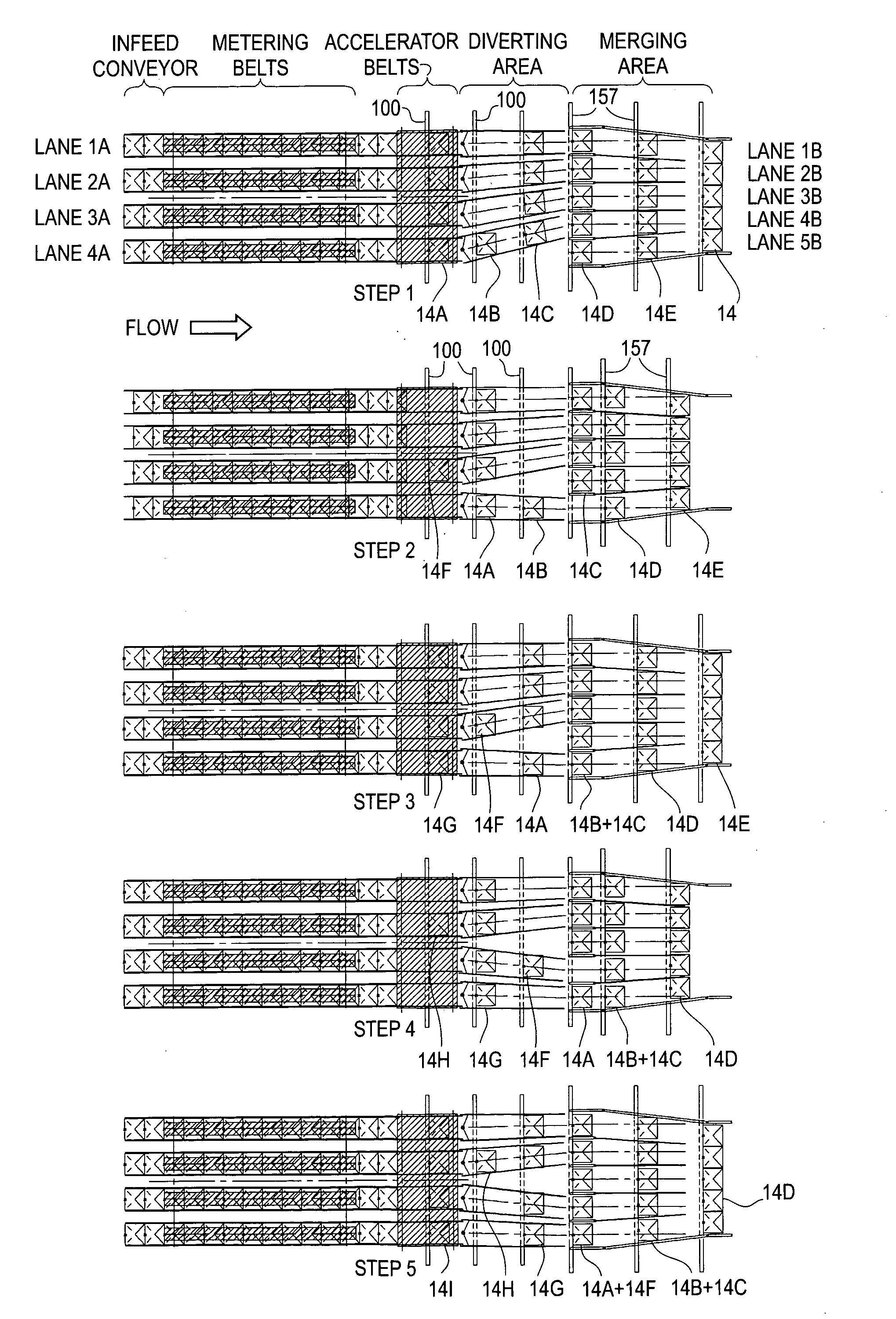
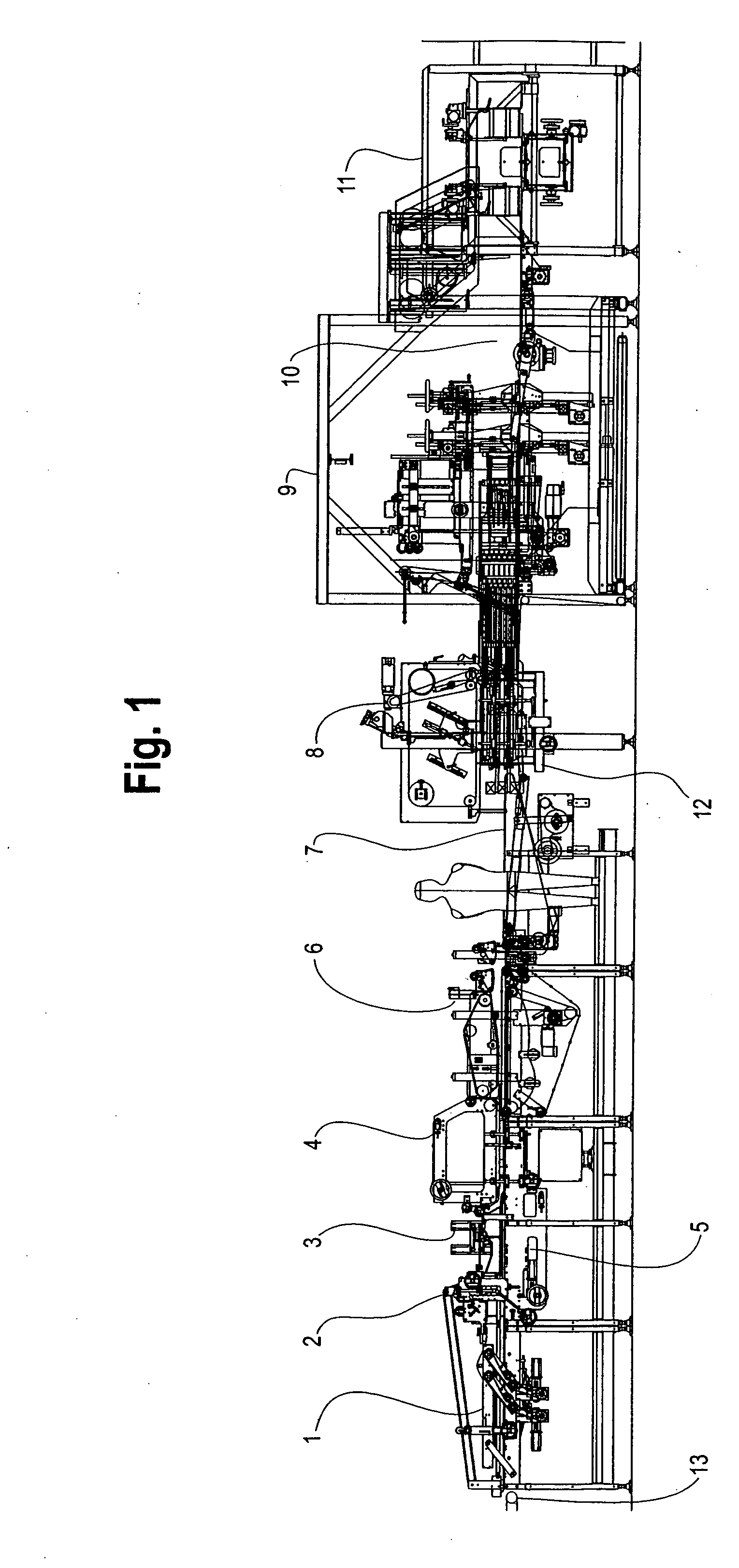
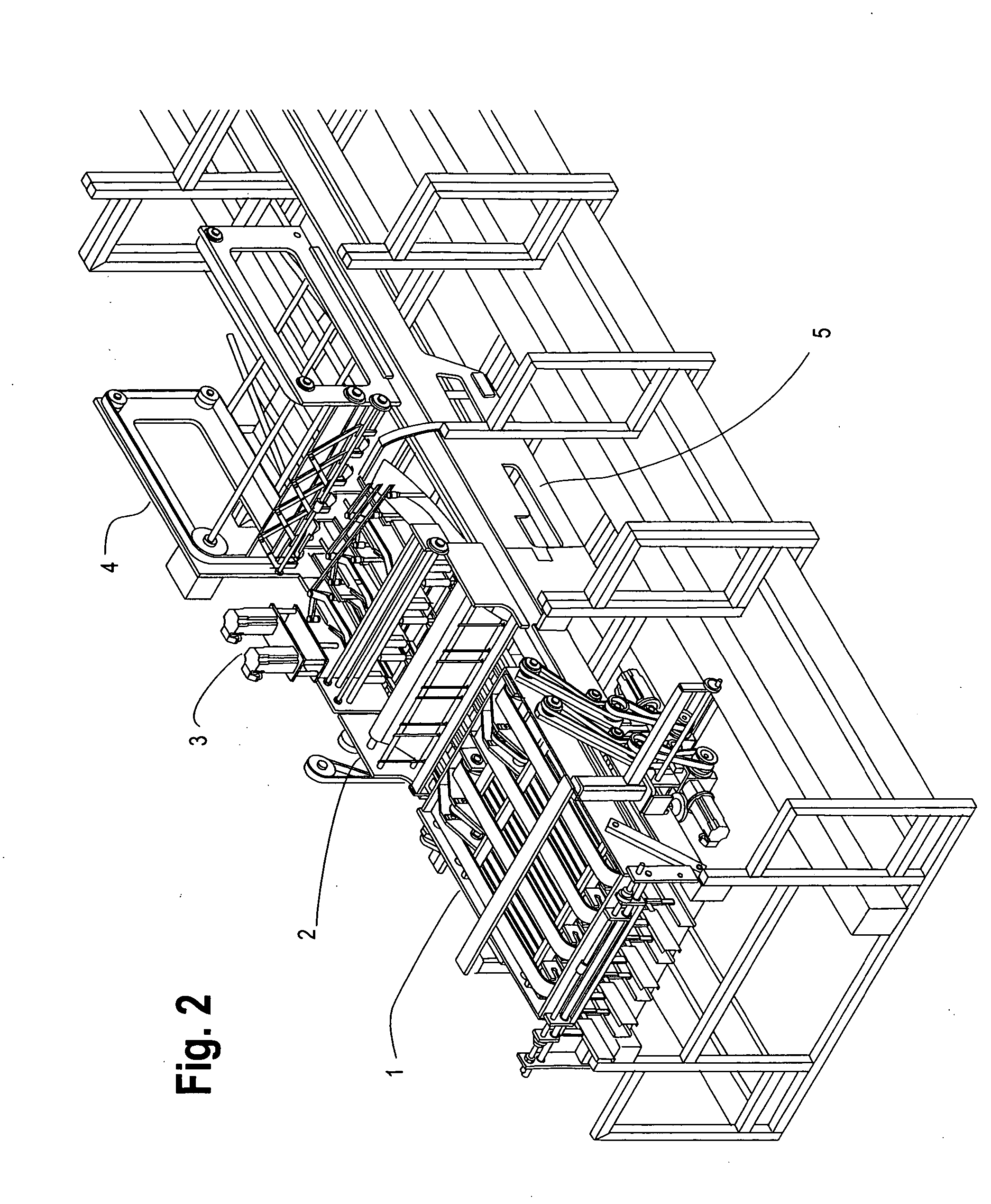
[0039]FIGS. 1-3 illustrate an inventive diverting station integrated in a conventional flow type wrapper, commonly known in the industry and described in U.S. Pat. No. 4,430,844. Product, such as rolled tissue or toweling, is randomly delivered to the wrapper in parallel lanes and presented to the wrapper in a side-by-side relationship by the infeed conveyor 13 at some average rate, where it enters a set of metering belts 1.

[0040] The metering belts are used for feeding items, or groups of items, one after the other to the accelerator belts 2. The metering belts are independently driven and capable of cycling continuously or intermittently to feed one or more items to the accelerator belts. The accelerator belts typically run at a surface speed that is slightly faster than the surface speed of metering belts, providing a gap between successive products to allow a lower, driven flighted conveyor 5 to actuate between successive products, to transport the product through diverting gat...


PUM


Abstract

A wrapping machine for wrapping products is provided with a product diverter for producing package formats which are greater in width than the number of lanes which deliver product to the wrapper machine. A plurality of metering belts advance product from an infeed conveyor along a plurality of infeed lanes. The metering belts are independently driven so that product can be advanced in each lane independently of the product in the other lanes. The metering belts deliver product to accelerator belts which speed up the product to create a gap between successive products in a lane. A first flighted conveyor advances product from the accelerator belts to a plurality of pivotally mounted diverting gates, corresponding in number to the number of infeed lanes. Each of the diverting gates direct the product to one of a plurality of output lanes. The number of output lanes is equal to, less than, or greater than the number of infeed lanes. The diverting gates are independently controlled so that each diverting gate can be pivoted independently of the other gates. A second flighted conveyor advances product from the discharge end of the diverter gates along the output lanes.

Description

BACKGROUND [0001] This invention relates to an apparatus and method to handle objects, such as rolled tissue product, within a wrapping machine that is capable of receiving at its input a substantially continuous flow of randomly spaced articles that are separated into a discrete number of lanes and discharging at its output side a continuous flow of articles separated into a discrete number of lanes which is equal to, less than, or greater than, the number of lanes at the infeed. A second objective of this apparatus is that the objects are discharged in an organized and timed relationship to further processing in the wrapping machine. SUMMARY OF PRIOR ART [0002] In all present art, in the production of products comprising tissue paper, a tissue web is wound into rolls of substantial width, commonly called “logs”, that are of appropriate diameter for consumer use. The full width “logs” are discharged from the rewinder, typically accumulated in a bucket type conveyor, and eventually ...

Claims


Application Information

Patent Timeline
Patent Type & Authority Applications(United States)
IPC IPC(8): B65G47/26B65G47/68
CPCB65B25/146B65B35/54B65G47/648B65G47/71
Inventor CHRISTMAN, BRIANWIERSCHKE, LARRY
Owner PAPER CONVERTING MASCH CO INC
Why Eureka
Try Eureka