Method and a device for lifting and/or lowering of objects at a wind turbine or the like and uses hereof

a technology for lifting and/or lowering objects, which is applied in the direction of mechanical equipment, machines/engines, transportation and packaging, etc., can solve the problems of time-consuming, relatively expensive and troublesome processes, increasing costs and complicating factors, and relatively large costs to be able, so as to achieve convenient transportation

Inactive Publication Date: 2006-08-10
PP ENERGY APS
View PDF3 Cites 95 Cited by
  • Summary
  • Abstract
  • Description
  • Claims
  • Application Information

AI Technical Summary

Benefits of technology

[0012] It is thus an object of the invention to provide a method and a device with which access to wind turbines on the whole or parts thereof, including especially wind turbine rotor blades, can be achieved with equipment which is relatively easy to transport.

Problems solved by technology

With such an arrangement, it is a time-consuming and relatively costly and troublesome process to have to undertake a cleaning of the rotor blades of a wind turbine.
Moreover, it is a cost-increasing and complicating factor that with such a known arrangement use must be made of mechanical equipment, for example a crane, with which to secure the suspension devices, in that these must be raised to a considerable height.
In connection herewith there will be a number of disadvantages, partly in that it will be a relatively large expense to be able to procure the necessary lifting equipment for these operations, and in that in many situations it can be troublesome not to say impossible to get the necessary lifting equipment to the site for the wind turbines.
Thus, it can be impossible or difficult to have to bring a crane to a wind turbine in the winter, in the spring and in the autumn, and on the whole under wet weather conditions.
Especially, it can be mentioned that it can be particularly problematic to have to undertake such actions at wind turbines, which are sea-based, in as much as here it must also be taken into consideration that it can be more difficult to operate at sea, and that it can be costly to have to undertake crane manoeuvres at sea.

Method used


Image

  • Method and a device for lifting and/or lowering of objects at a wind turbine or the like and uses hereof
  • Method and a device for lifting and/or lowering of objects at a wind turbine or the like and uses hereof
  • Method and a device for lifting and/or lowering of objects at a wind turbine or the like and uses hereof

Examples


Embodiment Construction

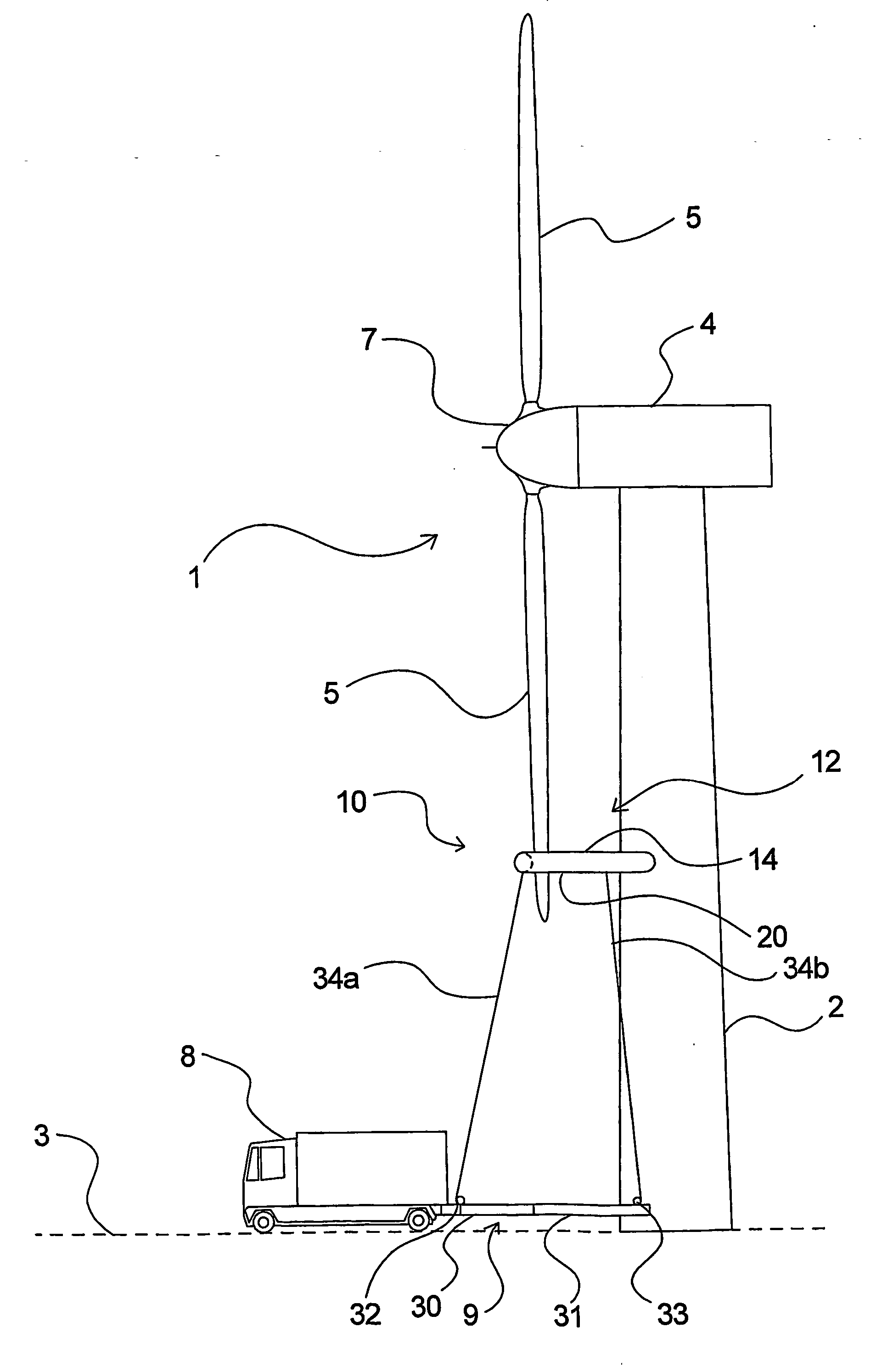
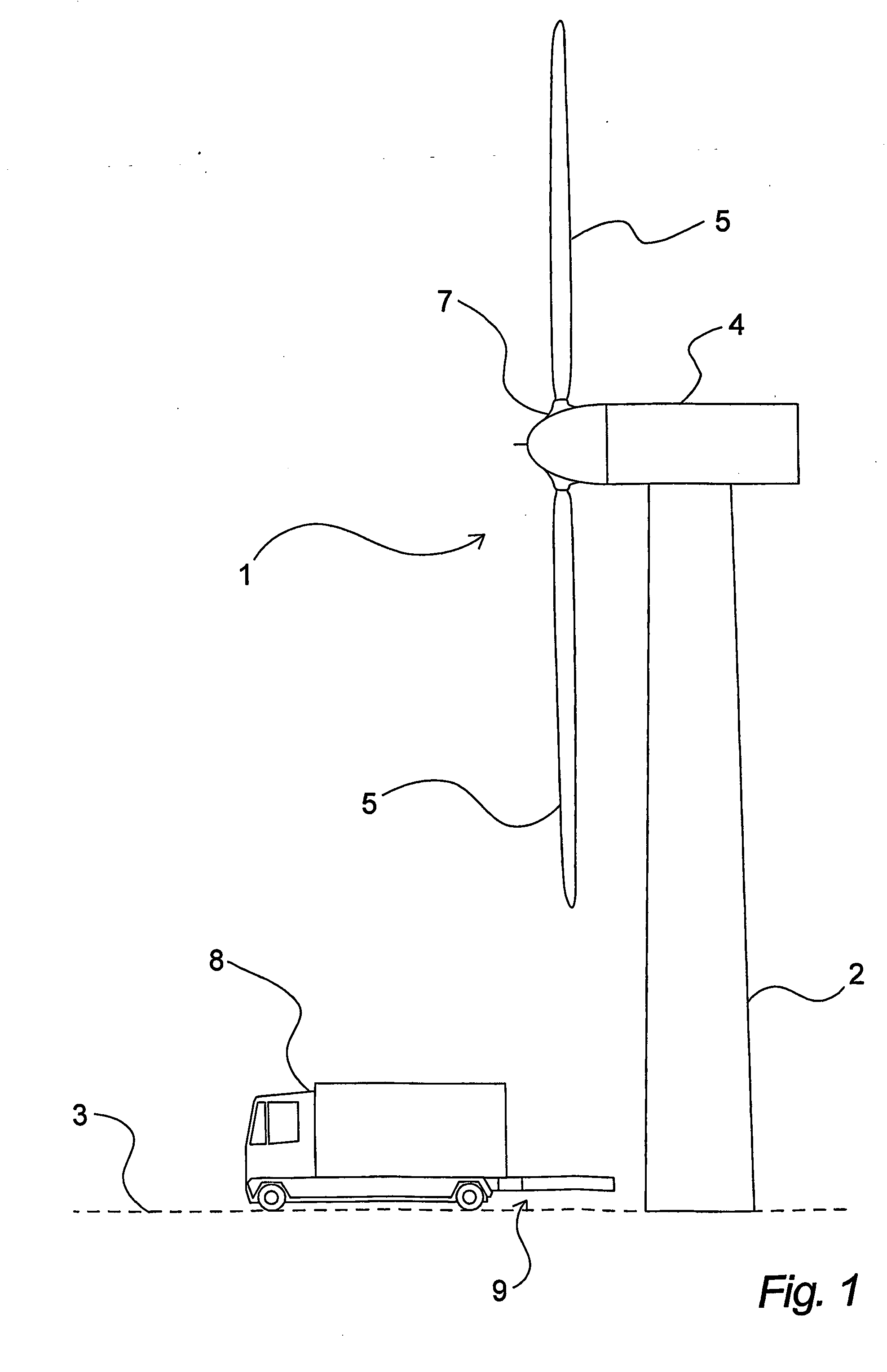
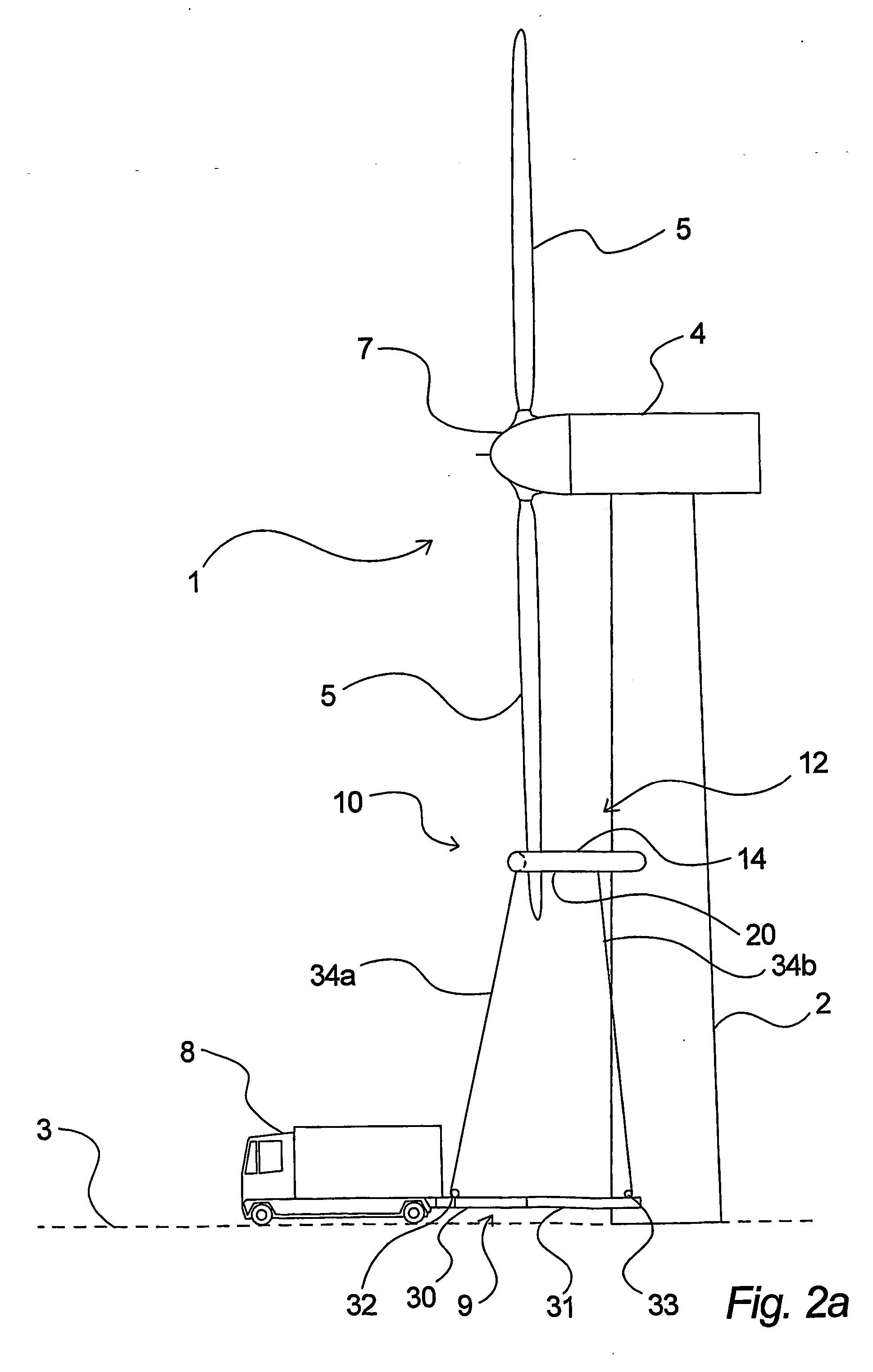
[0095] In FIG. 1 is shown a commonly known land-based wind turbine 1 seen from the side. Such a wind turbine 1 comprises a turbine tower 2 placed on a foundation on the ground 3. On the top of the turbine tower 2 a nacelle 4 is placed which contains generator, gear mechanisms, control equipment, bearings etc., and which in a commonly known manner can be turned depending on the direction of the wind. The nacelle 4 thus also supports the rotor hub 7 on which a number of rotor blades 5 are mounted—in the shown example three—as is most often the case. These rotor blades 5 are in a known manner arranged so that they can be turned substantially around a longitudinal axis with regard to wind speed etc. In connection with use of the invention, these rotor blades will most often be positioned so that they stand edgewise, i.e. turned so that the wind will blow substantially towards the leading edge (or trailing edge) of the rotor blades. Moreover, with the use of the invention, the nacelle 4 ...


PUM


Abstract

Method and device for lifting and/or lowering of objects in connection with a wind turbine or similar construction, where an uplift device is made to lift and/or lower itself in the proximity of the wind turbine or the similar construction, in as much as uplift device is possibly controlled in relation to the wind turbine or the similar construction and where at least one object is supported by said uplift device. The invention further relates to use hereof for lifting and/or lowering of various parts in connection with a wind turbine.

Description

FIELD OF THE INVENTION [0001] The invention relates to a method for lifting and / or lowering of objects in connection with a wind turbine or a similar construction. The invention also relates to a device for lifting and / or lowering of objects in connection with a wind turbine or a similar construction. Finally, the invention relates to uses of such a method and / or such a device. BACKGROUND OF THE INVENTION [0002] In connection with wind turbines, from time to time it will be necessary to undertake actions where it is desirable to be able to effect lifting and / or lowering of certain parts, elements, work equipment etc. For example, this can be the case with the inspection of wind turbine blades, with the cleaning of these, with various forms of treatment of, for example, wind turbine blades, in the replacement of parts such as, for example, a wind turbine blade etc. [0003] With regard to the cleaning of wind turbine blades, is shall thus be mentioned that it is generally recognized wi...

Claims


Application Information

Patent Timeline
Patent Type & Authority Applications(United States)
IPC IPC(8): B64B1/50B66F11/04F03D1/00
CPCB66C23/207B66F11/04F03D1/003Y02E10/72F03D80/50
Inventor TEICHERT, PAUL
Owner PP ENERGY APS
Why Eureka
Try Eureka