Rail mounting apparatus and method

Inactive Publication Date: 2006-08-10
LMT MERCER GROUP
View PDF99 Cites 28 Cited by
  • Summary
  • Abstract
  • Description
  • Claims
  • Application Information

AI Technical Summary

Benefits of technology

[0009] A rail mounting system is disclosed for mounting a rail (e.g., a stair, walkway, or fence railing) to a support structure, and a method for performing and using the same is also disclosed. The rail mounting system includes a novel bracket that serves as an intermediary apparatus between, e.g., a fence or banister rail, and a support structure. Thus, a rail may attach to the bracket after the bracket has been attached to a support structure (such a support structure may be, e.g., the side of a building, a post, a column, a beam, a wall or other rigid members to which a rail can be fixedly attached). The bracket is particularly usef

Problems solved by technology

However, various esthetic and structural difficulties have not been heretofore adequately addressed for securing such a synthetic rail and a bracket together.
Additionally, since the synthetic rail may have to be secured to the bracket at an angle other than perpendicular to a vertical support structure upon which the bracket is mounted (e.g., when providing railings for stairs between vertically positioned posts) such manual alignment of the rail is made even more difficult.
Another difficulty in assembling synthetic fences and railings results from the

Method used


Image

  • Rail mounting apparatus and method
  • Rail mounting apparatus and method
  • Rail mounting apparatus and method

Examples


Embodiment Construction

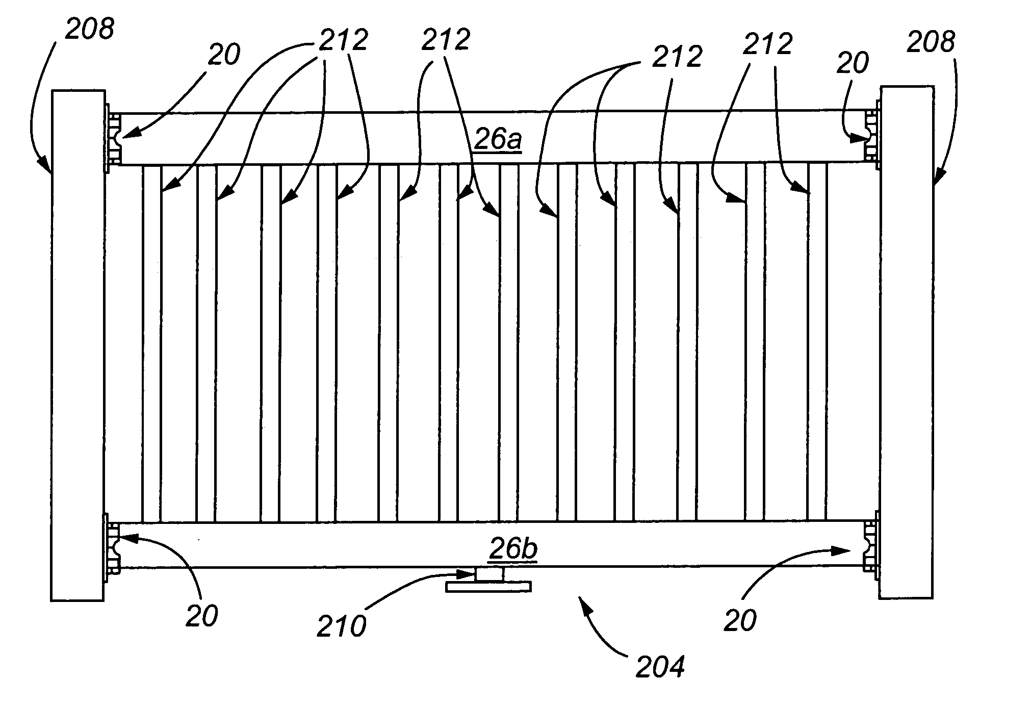
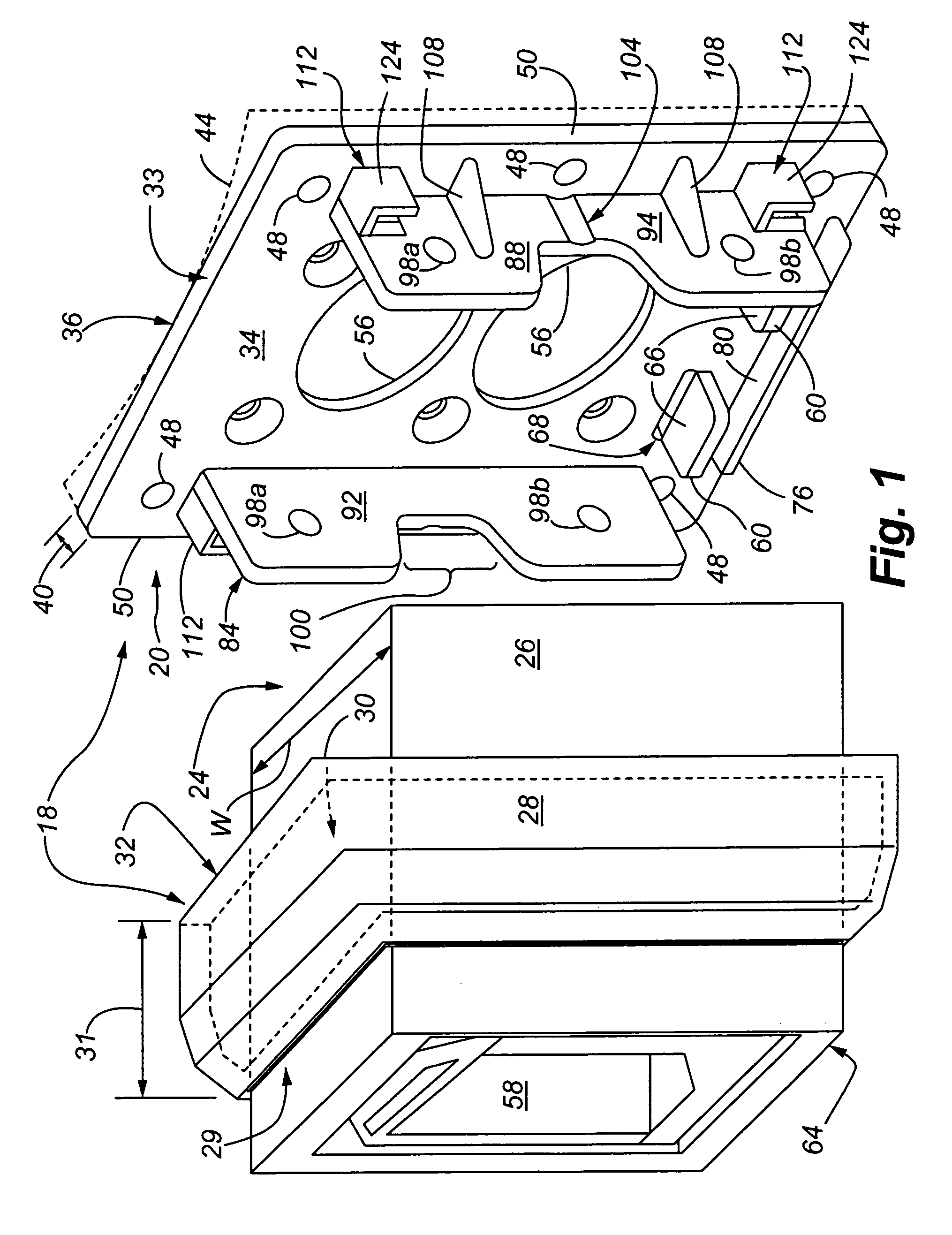
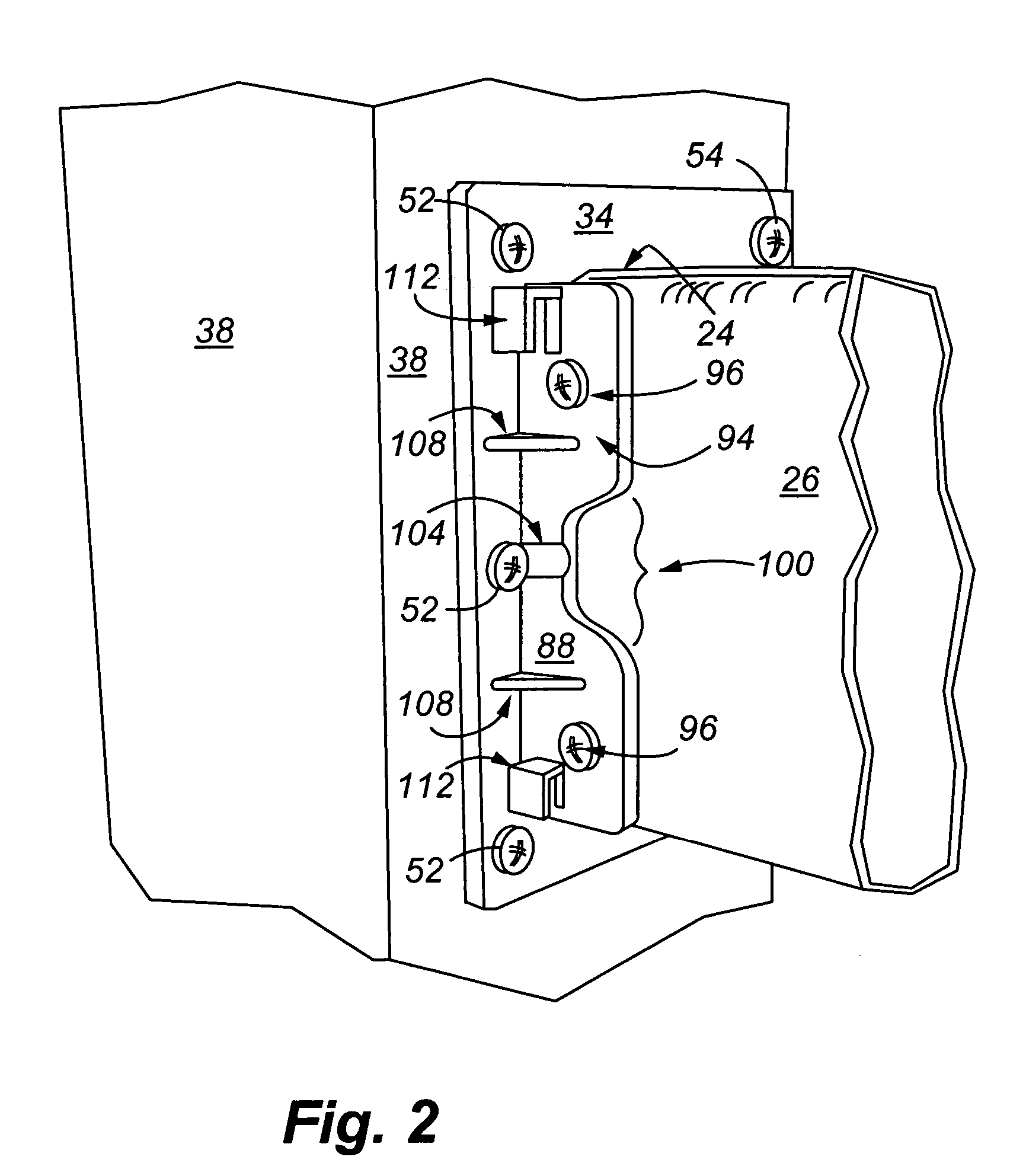
[0035]FIG. 1 shows an embodiment of the rail mounting system 18. The rail mounting system 18 includes a bracket 20 for mounting an end 24 of a rail 26 thereto (e.g., a synthetic rail, or alternatively, a wood, or metal rail). The rail 26 may be, e.g., up to ten feet in length (FIG. 1 does not show such a length of the rail 26 according to scale), and may have cross sectional dimensions of, e.g., less than eight inches by eight inches. The bracket 20 is correspondingly dimensioned to appropriately mate with the rail end 24. Additionally, the rail mounting system 18 includes a bracket cover 28 (e.g., FIGS. 1 and 8) for covering the bracket 20 once the rail end 24 is secured to the bracket 20 (as shown in FIG. 2). The bracket cover 28 may be manufactured from a moldable material(s) such as, e.g., vinyl, PVC, plastic, and the like. The bracket cover 28 includes a central channel 30 extending through the thickness 31 of the bracket cover, wherein a front end opening 29 of the central cha...


PUM


Abstract

A method and apparatus is disclosed for mounting a rail (e.g., fence, stair or banister) to a support structure (e.g., a post, wall, etc.), wherein a rail mounting bracket is provided that allows the rail to be supported within an interior of the bracket in a desired position until the rail can be fixedly secured to the bracket in the desired position. The bracket provides various projections from its face that allows a rail to be supported and fixed to the bracket at an upwardly and/or downwardly inclined angle relative to the bracket face. The bracket is designed to withstand various loads specified by building standards for composition fences and banisters.

Description

RELATED FIELD OF THE INVENTION [0001] The present invention relates to fence rail mounting apparatus and method, and in particular, to rail mounting bracket that is capable of withstanding substantial fence loadings without failure, and that allows rails to be mounted at various angles to the bracket. BACKGROUND [0002] Synthetic fences and railings having at least their exteriors made of vinyl, PVC, plastic or other synthetic materials (e.g., materials that can be molded in an injection mold, extruded or pultruded) are used as cost effective replacements for wood and / or metal fences and railings in numerous circumstances. Such synthetic fences and railings can be easier to install, and are substantially maintenance free. Such synthetic fences and railings are typically assembled from post and railing components, each such component made of a synthetic material(s) which typically can be, e.g., a molded, extruded or pultruded. Such synthetic post and railing components typically have ...

Claims


Application Information

Patent Timeline
IPC IPC(8): E04H17/14
CPCE04F11/1817E04H17/1421E04H2017/1452E04H2017/1491E04F2011/1819E04F11/1834E04F2011/1821E04H17/1452E04H17/1448E04H17/1417E04H17/1488
Inventor BURKART, MICHAEL G.HERION, JEFFREY G.
Owner LMT MERCER GROUP
Why Eureka
Try Eureka