Cursor for electronic devices

a cursor and electronic device technology, applied in the field of electronic devices, can solve the problems of small display, inability to present a large amount of information, and inability to accurately perceive etc., and achieve the effect of quick perception of the exact location of the displayed par

Inactive Publication Date: 2006-08-10
APPLE INC
View PDF12 Cites 23 Cited by
  • Summary
  • Abstract
  • Description
  • Claims
  • Application Information

AI Technical Summary

Benefits of technology

[0017] The present invention has several advantages over the prior-art solutions. With the present invention it is possible for the user to quickly perceive the exact location of the displayed part on the virtual desktop or in large digital material. Furthermore, the us

Problems solved by technology

The size of the display of an electronic device sets certain limits for presenting information on the display.
A small display is not the best place to present a large amount of information.
If the amount of information is large and all the information is presented on the display at the same time, detail may become illegible.
When the information to be presented on the display is considerably larger than the display area, the current location within the information is not well perceived.
However, the user is not provided with the information what the current location within the whole map is.
The aforementioned solutions have, however, se

Method used


Image

  • Cursor for electronic devices
  • Cursor for electronic devices
  • Cursor for electronic devices

Examples


Embodiment Construction

[0025] Reference will now be made in detail to the embodiments of the present invention, examples of which are illustrated in the accompanying drawings.

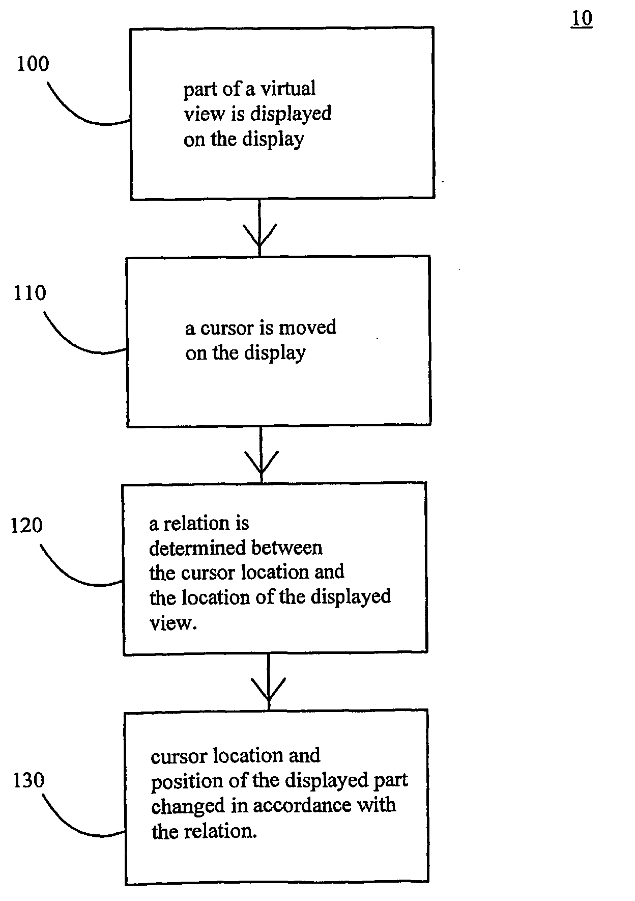
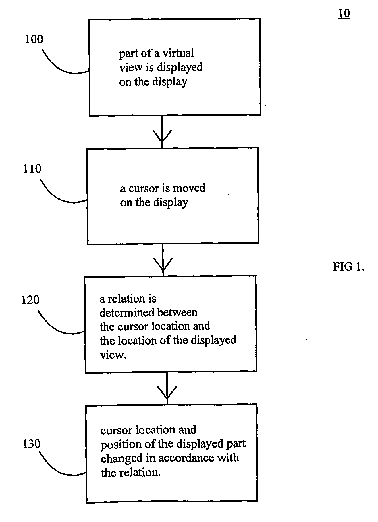
[0026] Referring to FIG. 1 and phase 100 a part of the entire virtual view is displayed on the display. This displayed part may be of any proportion or scale to the entire virtual view. In phase 110 the cursor is moved on the display. The cursor maybe moved by a mouse, selection of keys, touch pad, joystick or any other device suitable for moving a cursor. In phase 120 a relation is determined between the cursor location and the location of the displayed view.

[0027] In some embodiments the relation is linear in other embodiments progressive with deviation from origin or the like. In some embodiments the cursor, the virtual view, and / or the displayed part have the same origin. In phase 130 the cursor location and the position of the displayed part are changed in accordance with the said relation.

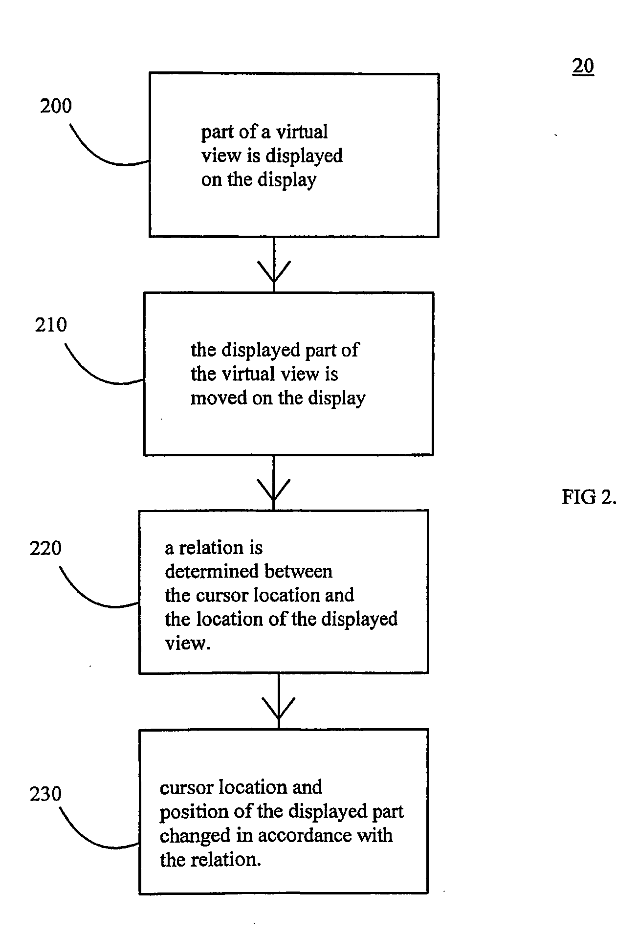
[0028] Referring to FIG. 2 and phase...


PUM


Abstract

The present invention describes a method, electronic device and computer program for displaying a cursor on the display of an electronic device. The size of the display is typically so small that only part of a virtual view is displayed at one time on the display. The user of the electronic device changes the displayed part of the virtual view on the display. In the present invention, a correlation between the cursor location on the display and the location of the displayed part of the virtual view within the whole virtual view is determined so that the cursor location on the display reflects the location of the displayed part of the virtual view in proportion to the whole virtual view. In other words, the user can quickly perceive the exact location e.g. on the virtual desktop or in large digital material displayed on the display of an electronic device.

Description

FIELD OF THE INVENTION [0001] The present invention relates to electronic devices. In particular, the present invention relates to a novel and improved method for computer programs and electronic devices to know the current location in a virtual view that is larger than the physical display. BACKGROUND OF THE INVENTION [0002] The size of the display of an electronic device sets certain limits for presenting information on the display. A small display is not the best place to present a large amount of information. If the amount of information is large and all the information is presented on the display at the same time, detail may become illegible. One solution to this problem is a so-called ‘virtual desktop’. There the total amount of the digital information is represented in a greater space than the actual amount of information presented on the display of the device at one time. Therefore, means for accessing the information represented outside the viewable area are needed. This is...

Claims


Application Information

Patent Timeline
IPC IPC(8): G06T15/00
CPCG06F3/0481G06F3/04812G06F3/0485G06F2203/04805
Inventor VAANANEN, JOHANNES
Owner APPLE INC
Why Eureka
Try Eureka