Drain assembly for rapid installation in sanitary vessels

a technology for sanitary vessels and drains, which is applied in water installations, book covers, constructions, etc., can solve the problems that none of the aforementioned solutions discloses a drain, and achieve the effects of reducing time and effort, enhancing aesthetics, and convenient installation and function

Active Publication Date: 2006-08-17
AS AMERICA
View PDF11 Cites 26 Cited by
  • Summary
  • Abstract
  • Description
  • Claims
  • Application Information

AI Technical Summary

Benefits of technology

[0010] It is an advantage of the present invention to provide a drain apparatus that significantly reduces the time and effort associated with installation thereof, as compared to conventional drain stopper mechanisms. Such a drain apparatus desirably obviates the need for tools, plumber's putty or caulk to ensure proper alignment and sealing characteristics.
[0011] It is another advantage of the present invention to provide a drain apparatus that readily installs and functions in a plurality of sanitary vessel configurations without detracting from the aesthetic appeal thereof. Such a drain apparatus desirably imparts enhanced aesthetic qualities in applications where the drain apparatus is visible beneath a sanitary vessel within which the drain apparatus is employed.
[0012] It is a further advantage of the present invention to provide a drain apparatus that facilitates actuation of a stopper portion thereof without compromising seal integrity. Such a drain apparatus desirably induces sufficient tightening of the appropriate elements thereof so as to effect a leak proof seal upon initial installation in a sanitary vessel.
[0013] In accordance with these and other advantages, the present invention provides an improved drain assembly for use in sanitary vessel. The drain assembly of the present invention comprises a drain stopper assembly having an elongate one-piece housing with a longitudinal axis defined therealong. The housing has a proximate extent for disposal proximate a vessel surface, an opposing distal extent for disposal proximate a waste outlet and a longitudinal body coextensive extent with both of the proximate and distal extents and defining a lumen therein. The housing body includes each of an inner circumferential surface of predetermined inner diameter and an outer circumferential surface of predetermined outer diameter. A flange portion at the proximate extent has a fluid egress for delivery of fluids from the sanitary vessel to the housing lumen. The drain stopper assembly further includes a linearly reciprocable drain stopper having a closure head from which an elongate shaft depends generally normally so that a longitudinal axis thereof is coincident with the housing longitudinal axis. The shaft has a proximate extent adjacent the closure head and an opposing free extent disposed in the housing lumen. The stopper reciprocates between a fully closed position, wherein the closure head obstructs the fluid egress, and a fully open position, wherein the fluid egress remains unobstructed. A securement region provided on the outer housing surface has a receiving region defined therewith.

Problems solved by technology

Although consumers must often make difficult decisions concerning the extent to which certain functional and aesthetic features can feasibly be incorporated into a product, the same consumers repeatedly demand ease of installation and maintenance of the

Method used


Image

  • Drain assembly for rapid installation in sanitary vessels
  • Drain assembly for rapid installation in sanitary vessels
  • Drain assembly for rapid installation in sanitary vessels

Examples


Embodiment Construction

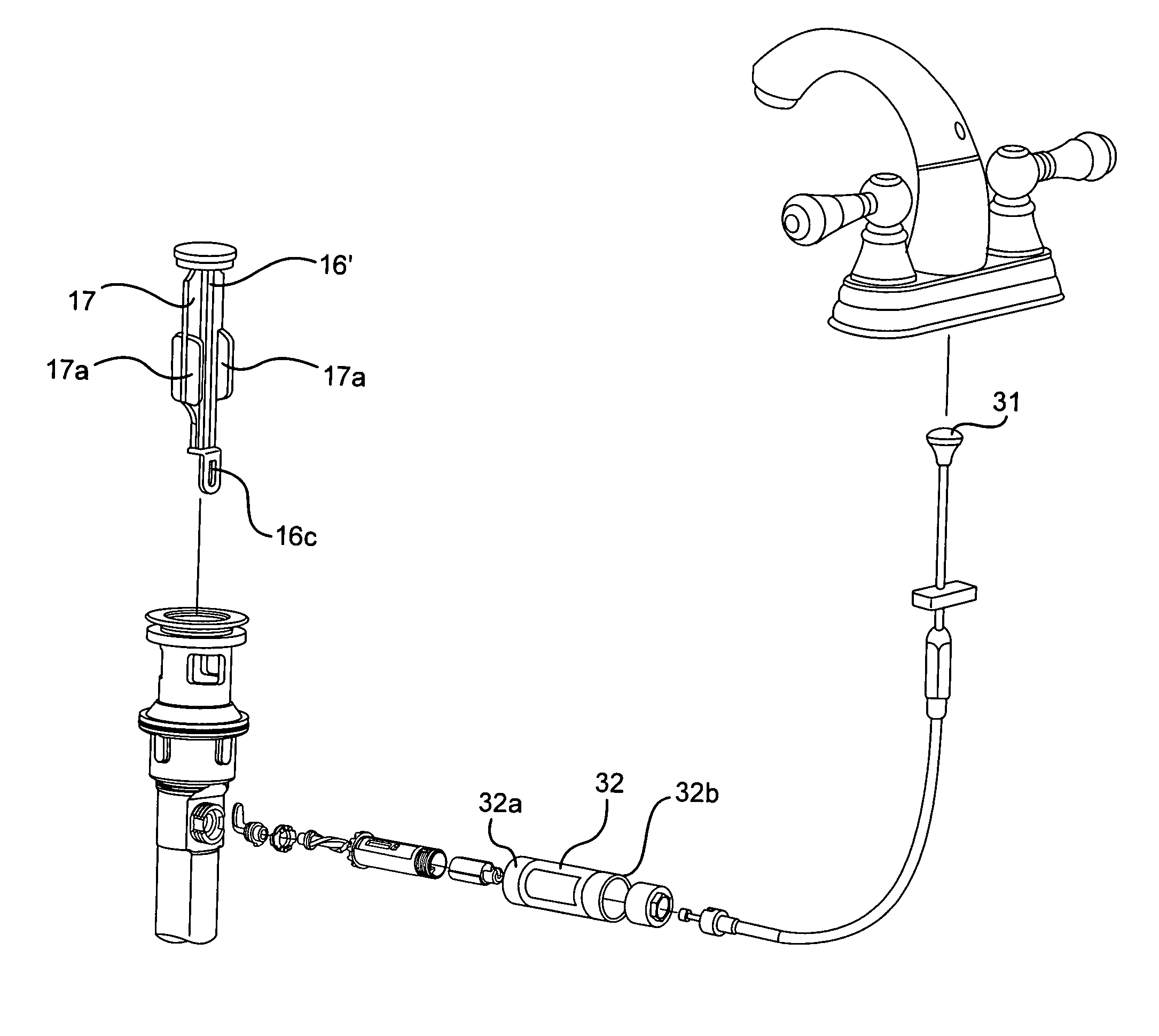
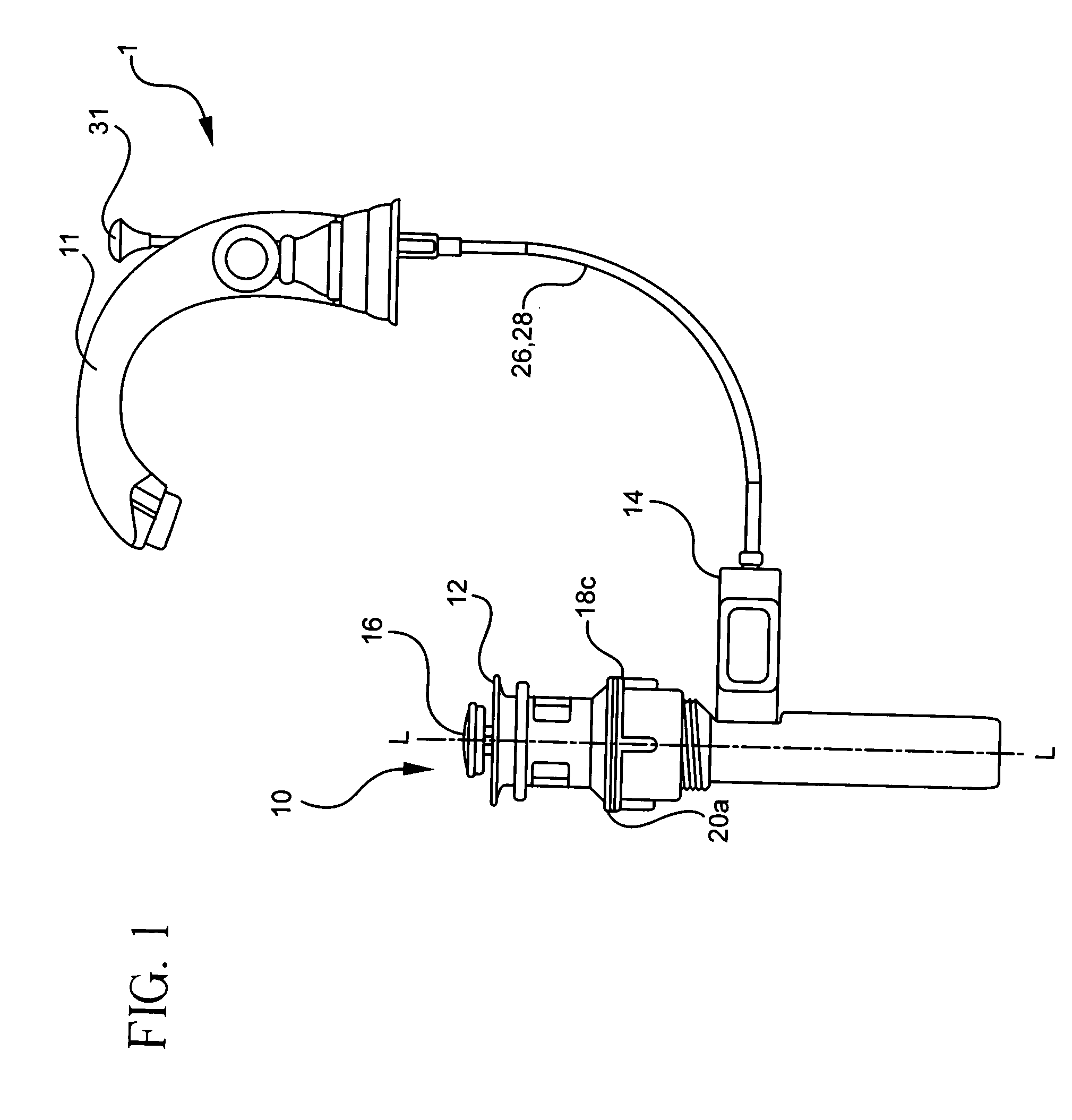
[0034] Now referring to the figures, wherein like numerals identify like elements, FIG. 1 shows a drain apparatus and sanitary fitting system 1 that includes drain assembly 10 of the present invention for use within a sanitary vessel, such as a sink or basin S (shown in FIGS. 5A and 6). Drain assembly 10 is depicted in combination with sanitary fitting 11, shown herein as a dual handle lavatory faucet. It is understood, however, that sanitary fitting 11 may comprise any configuration that is amenable to successful operation of the present invention, including but not limited to kitchen faucets, bath fillers, bidet fittings and the like.

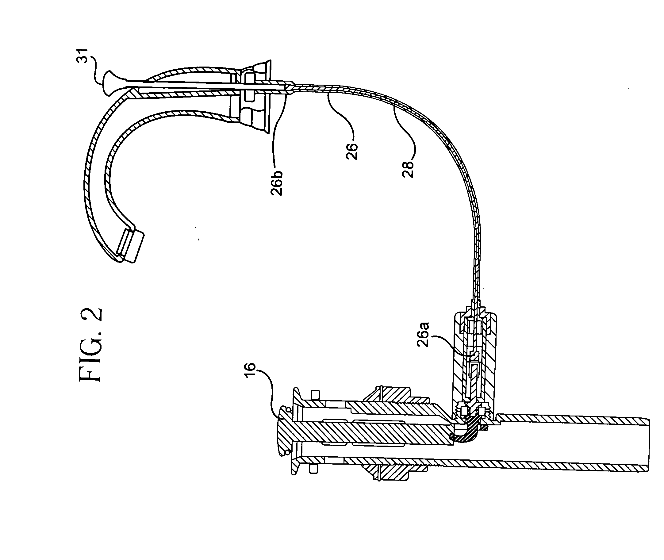
[0035] Drain assembly 10 includes a drain stopper assembly 12 detachably coupled with an actuation assembly 14 such that operation of the latter effects reciprocal motion of drain stopper 16. Movement of stopper 16 between open and closed positions corresponds to actuation of a rotating knob or lift member in communication with actuation assembly 14,...


PUM


Abstract

The present invention provides an improved drain assembly having a drain stopper assembly in operational communication with an actuation assembly. The drain stopper assembly includes an elongate one-piece housing with a longitudinal body coextensive with proximate and distal extents of the housing and defining a lumen therein. A flange portion at the proximate extent has a fluid egress for delivery of fluids from a sanitary vessel to the housing lumen. The housing body has an inner circumferential surface of predetermined inner diameter and an outer circumferential surface of predetermined outer diameter. A linearly reciprocable drain stopper is provided that has a closure head proximate which an elongate shaft depends. The stopper reciprocates between a fully closed position, wherein the closure head obstructs the fluid egress, and a fully open position, wherein the fluid egress remains unobstructed. A securement region provided on the outer housing surface has a receiving region defined therewith and effects operational communication between the drain stopper assembly and the actuation assembly so that operation of a drain articulation member effects reciprocal motion of the drain stopper. In this embodiment, the housing, flange portion and securement region comprise an integral member. In an alternative embodiment, the drain stopper assembly has a multi-piece housing.

Description

[0001] This application claims priority to Applicant's U.S. Application Ser. No. 60 / 652,402, filed Feb. 11, 2005, and incorporated by reference herein.FIELD OF THE INVENTION [0002] The present invention is directed to an apparatus for effecting effortless installation of a drain apparatus in a sanitary vessel such as a sink or basin. The drain apparatus of the present invention incorporates structure that attenuates the time required for installation and / or maintenance of conventional drain assemblies without compromising the function thereof. In this manner, the present invention enhances the operation of newly installed and pre-installed sanitary vessels. BACKGROUND OF THE INVENTION [0003] Installation and maintenance of sanitary vessels requires substantial investments of fiscal and temporal resources. Although consumers must often make difficult decisions concerning the extent to which certain functional and aesthetic features can feasibly be incorporated into a product, the sam...

Claims


Application Information

Patent Timeline
IPC IPC(8): E03C1/23
CPCE03C1/2304B42D3/14B42D9/002
Inventor JACOBS, BARRY H.
Owner AS AMERICA
Why Eureka
Try Eureka