
Brake plate

a technology of brake plate and carrier plate, which is applied in the field of brake plate, can solve the problems of not being able to adapt the holding structure of the brake plate carrier plate, the friction lining to shear off from the brake lining carrier plate, and the edge lifting

Inactive Publication Date: 2006-08-17
AML LANXIDE EURO
View PDF20 Cites 28 Cited by
  • Summary
  • Abstract
  • Description
  • Claims
  • Application Information

AI Technical Summary

Benefits of technology

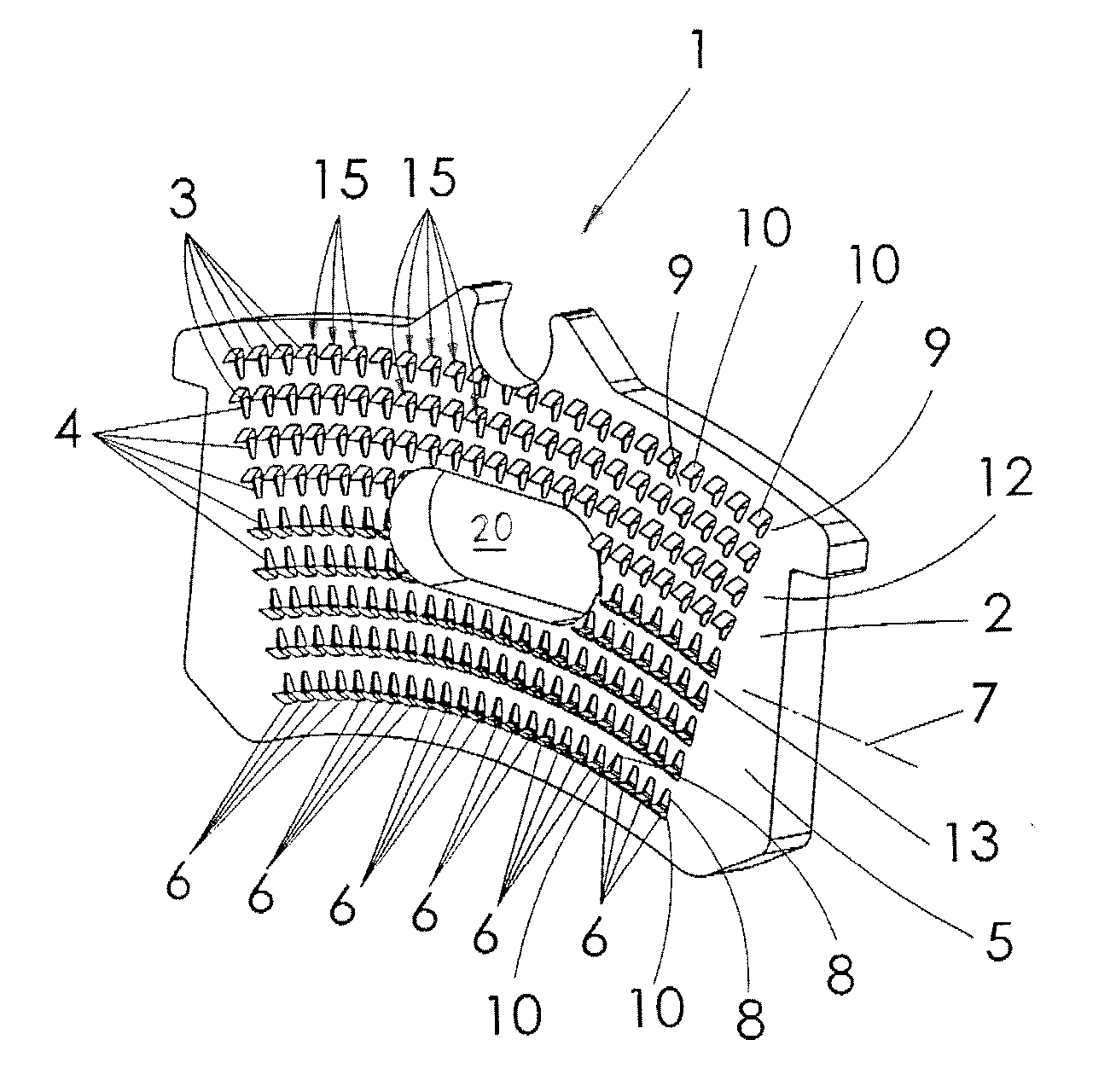
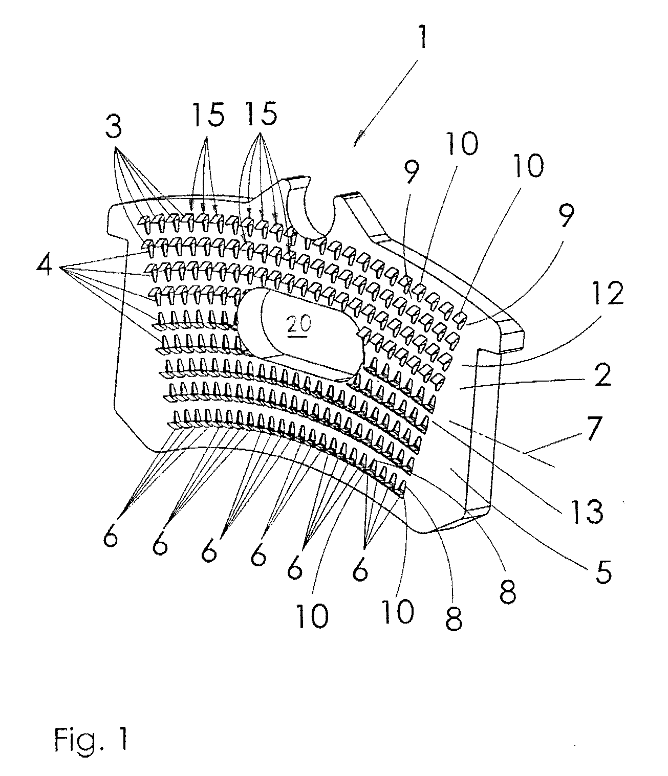
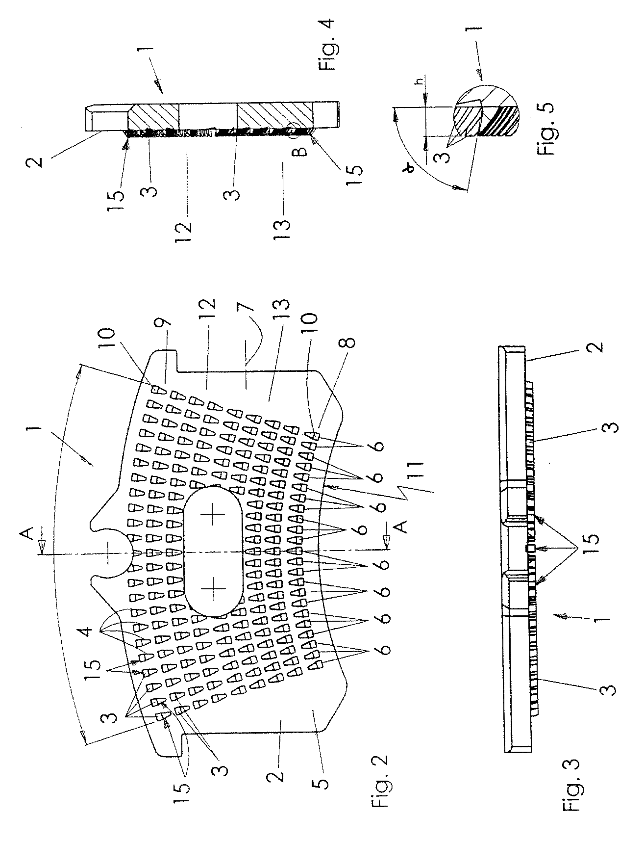
[0007] According to one aspect of the invention, a brake lining carrier plate is provided wherein the holding structures in the rows are arranged in such a way that there is a protrusion at the beginning and at the end of each row. In this manner, the holding structures can be adapted to the outer contour of the friction lining without the rows beginning or ending with depressions. This counteracts an accumulation of moisture in front of the first protrusion at the beginning of the rows or behind the last protrusion at the end of the rows.
[0008] According to a first embodiment of the invention, the holding structures have at least two sections with an opposing arrangement of the protrusion and of the depression of the holding structures. As long as the opposing sections are arranged at the opposite ends of the rows, the manufacturing process can then easily fulfill the requirement that there should be a protrusion (or a crimp) at the beginning and at the end of each row. Moreover, as a result, the holding bond effectuated between the brake lining carrier plate and the friction lining by the holding structures can withstand greater stress. In this manner, the friction lining can absorb greater braking forces without the friction lining shearing off from the brake lining carrier plate.

Problems solved by technology

Brake lining carrier plates entail the risk that so-called edge lifting of the friction lining occurs on the brake lining carrier plate, which can cause the friction lining to shear off from the brake lining carrier plate when subjected to high braking torques.
Edge lifting also possibly may be caused by rusting of the brake lining carrier plate brought about by said moisture penetration.
As a result, it is not possible to adapt the holding structures on the brake lining carrier plate to the outer contour of the friction lining in such a manner as to avoid the edge lifting effect.
Moisture can accumulate in said depression between the lining carrier plate and the brake lining, thus causing an edge lifting effect.
Moreover, through the alignment of the rows of the holding structures in the lengthwise direction, the crosswise edges of the brake lining, which are especially stressed during braking, are affected, so that the risk of the brake lining shearing off from the brake lining carrier plate is especially great.
As a result, there is also a risk of an edge lifting effect there since moisture can accumulate in the depressions arranged in the edge area of the brake lining.

Method used


Image

  • Brake plate
  • Brake plate
  • Brake plate

Examples


Embodiment Construction

[0045] FIGS. 1 to 4 show a brake lining carrier plate 1 to hold a friction lining of the type used, for example, in a vehicle brake system. Such a brake system can be, for instance, a disk brake. As a matter of principle, the brake lining carrier plate 1 can also be employed in a drum brake or in another type of brake system.

[0046] The brake lining carrier plate 1 has holding structures 15 arranged in rows 6 on the lining side 2 for the friction lining (not shown here). Each holding structure 15 has a protrusion 3 and a depression 4, whereby the protrusion 3 is made in the carrier plate surface 5 through the displacement of material, thereby forming the depression 4. To form the brake structure, said protrusion 3 engages with the friction lining (not shown here).

[0047] The rows 6 run essentially crosswise to the longitudinal axis 7 of the brake lining carrier plate 1, and are arranged in a fan formation, namely, in such a way that the rows 6—relative to the installation position o...


PUM


Abstract

The invention relates to a brake lining carrier plate 1 to hold a friction lining, especially for installation into a vehicle brake system, with holding structures 15, 16 for the friction lining arranged in rows 6 on the lining side 2, whereby each holding structure 15, 16 has a protrusion 3 and a depression 4, whereby the protrusion 3 is made when the depression 4 is formed in the surface 5 through the displacement of material. Said protrusion 3 engages with the friction lining. The holding structures 15, 16 in the rows 6 are arranged in such a way that there is a protrusion 10 at the beginning 8 and at the end 9 of each row 6. In one embodiment, the rows 6 run essentially crosswise to the longitudinal axis 7 of the brake lining carrier plate 1.

Description

[0001] The invention relates to a brake lining carrier plate to hold a friction lining, especially for installation into a vehicle brake system. The brake lining carrier plate has holding structures for the friction lining arranged in rows on the lining side, whereby each holding structure has a depression and a protrusion, the protrusion being made when the depression is formed in the surface through the displacement of material. Said protrusions engage with the friction lining. TECHNICAL BACKGROUND [0002] Brake lining carrier plates entail the risk that so-called edge lifting of the friction lining occurs on the brake lining carrier plate, which can cause the friction lining to shear off from the brake lining carrier plate when subjected to high braking torques. Edge lifting refers to the separation of the friction lining at its outer contour or in the area of its edges from the brake lining carrier plate. Such edge lifting may be caused by the penetration of moisture, water, salt...

Claims


Application Information

Patent Timeline
IPC IPC(8): F16D65/04
CPCF16D2069/0441F16D69/0408B21J5/068
Inventor JUNG, FRIEDRICH H.
Owner AML LANXIDE EURO
Learn More