
Shock absorbing steering apparatus

Inactive Publication Date: 2006-08-17
TOYOTA JIDOSHA KK
View PDF18 Cites 35 Cited by
  • Summary
  • Abstract
  • Description
  • Claims
  • Application Information

AI Technical Summary

Benefits of technology

[0004] In the first conventional apparatus, the energy absorbing plate is required to be securely welded or otherwise fixed to the upper portion of the outer circumferential surface of the steering column, more precisely, of the column body. This requirement reduces ease of assembling of the steering apparatus. In the second conventional apparatus, the energy absorbing plate is required to be fastened to the vehicle body while the steering column is fixed to the vehicle body. This requirement increases complexity of the procedure to assemble the steering apparatus with respect to the vehicle body. While the first and second conventional apparatuses described above suffer from those drawbacks, various other conventional steering apparatuses also suffer from specific drawbacks. In this respect, improvements to overcome the drawbacks of the conventional steering apparatuses are needed to provide an improved steering apparatus provided with an impact energy absorbing member.
[0006] In the shock absorbing steering apparatus of the present invention constructed as described above, the impact energy absorbing member is mounted on only one of the steering column and the relevant portion of the vehicle body, so that the steering apparatus can be easily assembled with respect to the vehicle body. Further, the impact energy absorbing member is not required to be welded or otherwise fixed to one of the steering column and the portion of the vehicle body, so that the impact energy absorbing member can be simply and economically held in position. In addition, the impact energy absorbing member is not required to be fastened to the other of the steering column and the portion of the vehicle body, so that steering column can be easily assembled with respect to the vehicle body. Thus, the present shock absorbing steering apparatus is improved in construction over the conventional counterparts.

Problems solved by technology

This requirement reduces ease of assembling of the steering apparatus.
This requirement increases complexity of the procedure to assemble the steering apparatus with respect to the vehicle body.
While the first and second conventional apparatuses described above suffer from those drawbacks, various other conventional steering apparatuses also suffer from specific drawbacks.

Method used


Image

  • Shock absorbing steering apparatus
  • Shock absorbing steering apparatus
  • Shock absorbing steering apparatus

Examples


first embodiment

[0196] i) Arrangement of Shock Absorbing Steering Apparatus of the First Embodiment

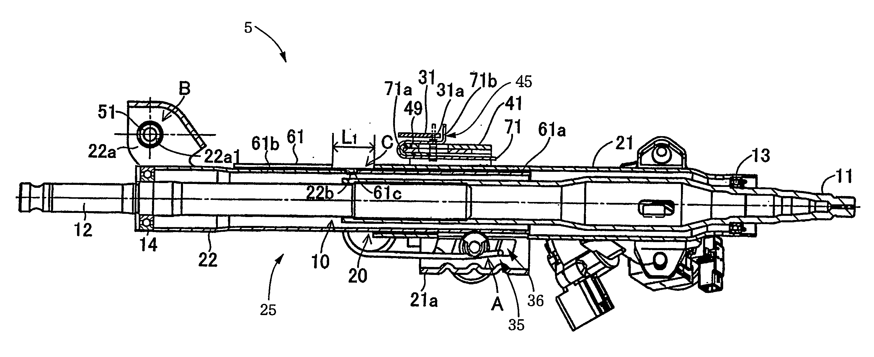
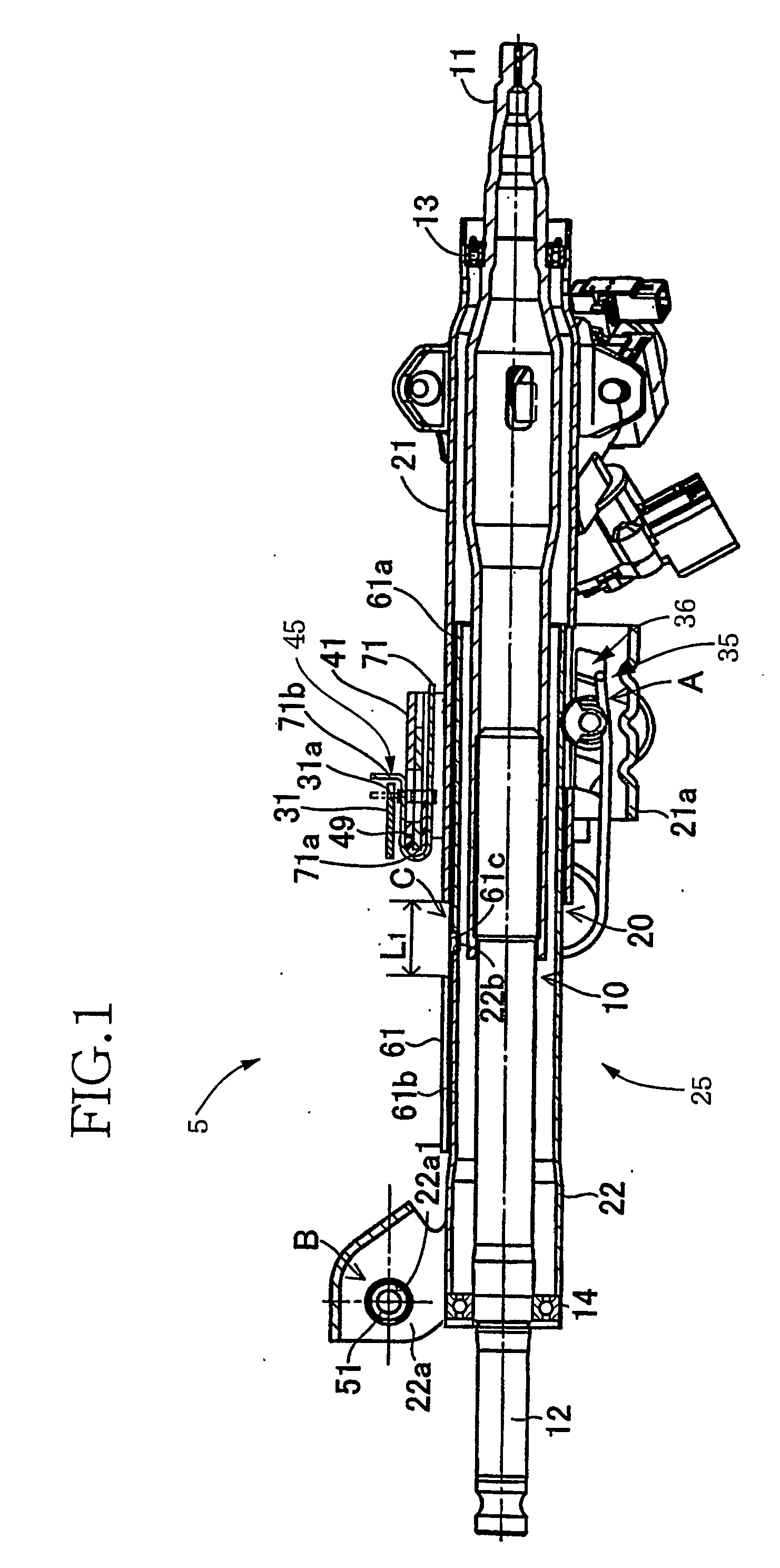
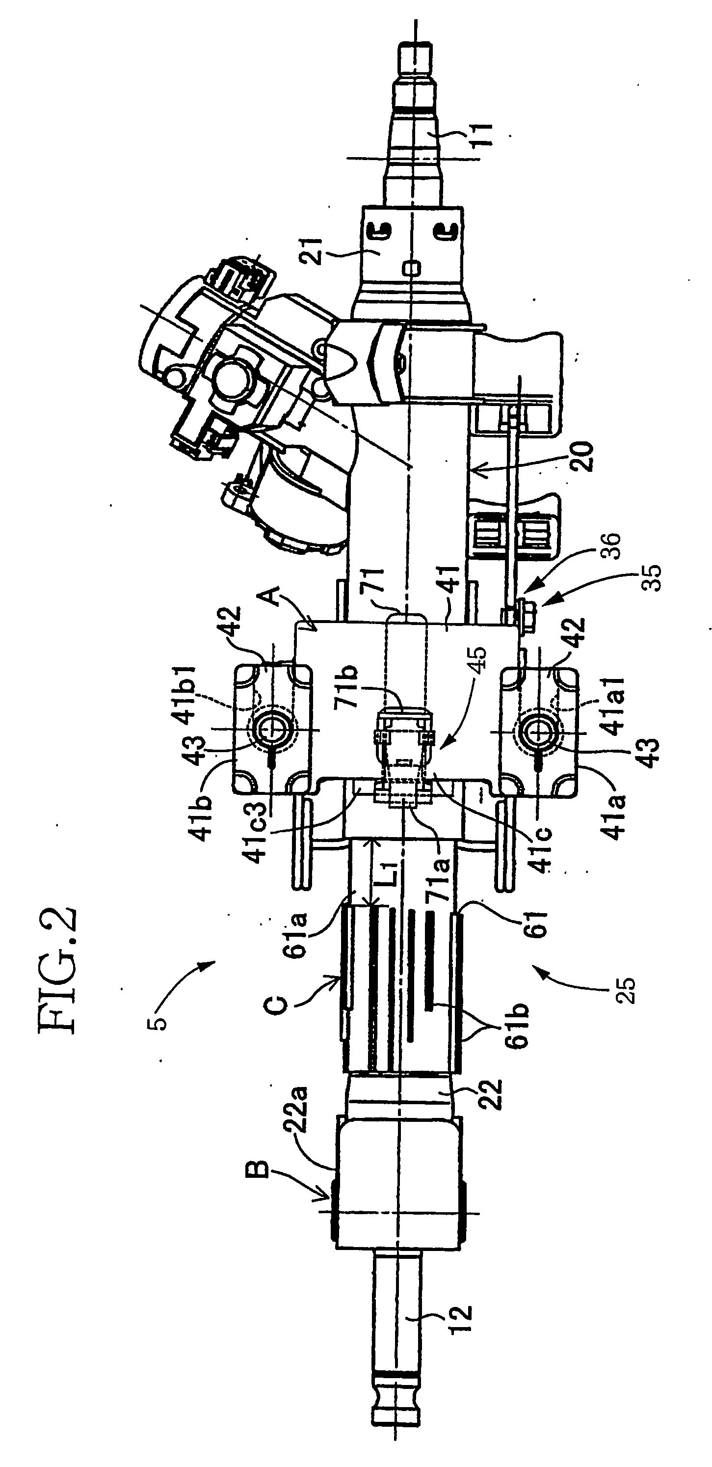
[0197] Referring first to FIGS. 1-6, there is shown a shock absorbing steering apparatus constructed according to a first embodiment of this invention. In this first embodiment, the steering apparatus includes a steering shaft 10 having an upper shaft 11 and a lower shaft 12 which are axially movable relative to each other and rotatable together so as to transmit a torque. Thus, the steering shaft 10 is contractible and extensible in the axial direction. The steering shaft 10 is freely rotatably supported by a steering tube 20 having an outer tube 21 and an inner tube 22 which are axially movable relative to each other. Thus, the steering tube 20 is also contractible and extensible in the axial direction. The steering shaft 10 and the steering tube 20 cooperate to constitute a column body 25. This column body 25 is assembled with respect to a body of a motor vehicle such that the column body 25 is in...

second embodiment

[0247] In the first embodiment, the upper arm section 71a2 of the U-shaped energy absorbing plate 71 is positioned by the pair of upper holding pieces 49b1, 49b2 of the guide member 49, as shown in FIG. 3. In a second embodiment shown in FIG. 12, however, the upper arm section 71a2 is supported by positioning and holding means in the form of a rectangular three-sided clip 81. In the other aspects, the shock absorbing apparatus according to the present second embodiment is identical in construction and operation with that of the first embodiment described above, and the second embodiment has the advantages [1] through [13] described above with respect to the first embodiment.

[0248] The rectangular three-sided clip 81 is formed from a metallic sheet into a structure having three sides consisting of one side in the form of an elastically deformable intermediate curved section 81a, and two opposed sides connected by the curved section 81a, as shown in FIG. 13. The curved section 81a is...

third embodiment

[0252] A third embodiment of this invention is shown in FIG. 15. In this third embodiment, the upper arm section 71a2 of the energy absorbing plate 71 is positioned and held with respect to the break-away bracket 41 by positioning and means in the form of a holding band 91. In the other aspects, the third embodiment is identical in construction and operation with the first embodiment, and has the advantages [1] through [13] described above with respect to the first embodiment.

[0253] The holding band 91 is variable in its effective length of holding, and is arranged to hold together the upper arm section 71a2 of the energy absorbing plate 71 and a support piece 41c1a formed on the upper plate 41c1 of the break-away bracket 41. This support piece 41c1a functions as the supporting portion provided on the mounting portion 45. The holding band 91 is broken down or fractured when a load larger than a predetermined threshold acts on the holding band 91. That is, the holding band 91 is bro...


PUM


Abstract

A shock absorbing steering apparatus for use in a vehicle, including a steering column to be fixed to a portion of a body of the vehicle such that the steering column is releasable from the body of the vehicle and movable in a forward direction of the vehicle in the event of a secondary collision of an occupant of the vehicle upon a collision of the vehicle, and wherein one of the steering column and the portion of the vehicle body includes a mounting portion, while the other of the steering column and the portion of the vehicle body includes a holding portion. The steering apparatus further includes an impact energy absorbing member to be mounted on the mounting portion. The impact energy absorbing portion includes an engaging portion engageable with the holding portion and is deformable as the steering column is moved in the forward direction while the engaging portion is held in engagement with the holding portion, whereby the impact energy absorbing member absorbs an impact energy generated by the secondary collision.

Description

TECHNICAL FIELD [0001] The present invention relates to a shock absorbing steering apparatus for use in a vehicle, which includes a steering column as a major element and which is provided with an impact energy absorbing member arranged to absorb an impact energy generated by a secondary collision of an occupant (operator or driver) of the vehicle, upon a collision of the vehicle. BACKGROUND ART [0002] The steering apparatus of this type is arranged such that in the event of a secondary collision of the vehicle occupant or operator, for example, with the steering wheel attached to the steering column, the steering column is releasable from the body of the vehicle, and axially movable in the forward direction of the vehicle, while a force of resistance to this movement of the steering column (namely, an impact energy absorbing load) is generated. That is, an impact energy absorbing member is provided to absorb an impact energy generated by the secondary collision. Described more spec...

Claims


Application Information

Patent Timeline
IPC IPC(8): B62D1/19B62D1/16
CPCB62D1/195
Inventor IMAMURA, KENJIHOSHINO, SHIGERUYOSHINO, KIMINORIKONDO, HIDEONAKANO, JUNICHIDATE, HIROAKINAKANISHI, HITOSHI
Owner TOYOTA JIDOSHA KK
Learn More