
Electrochromatic polymer mirror surface for vehicle blind spot exposure

Inactive Publication Date: 2006-08-17
MALHAS KHALED
View PDF11 Cites 7 Cited by
  • Summary
  • Abstract
  • Description
  • Claims
  • Application Information

AI Technical Summary

Benefits of technology

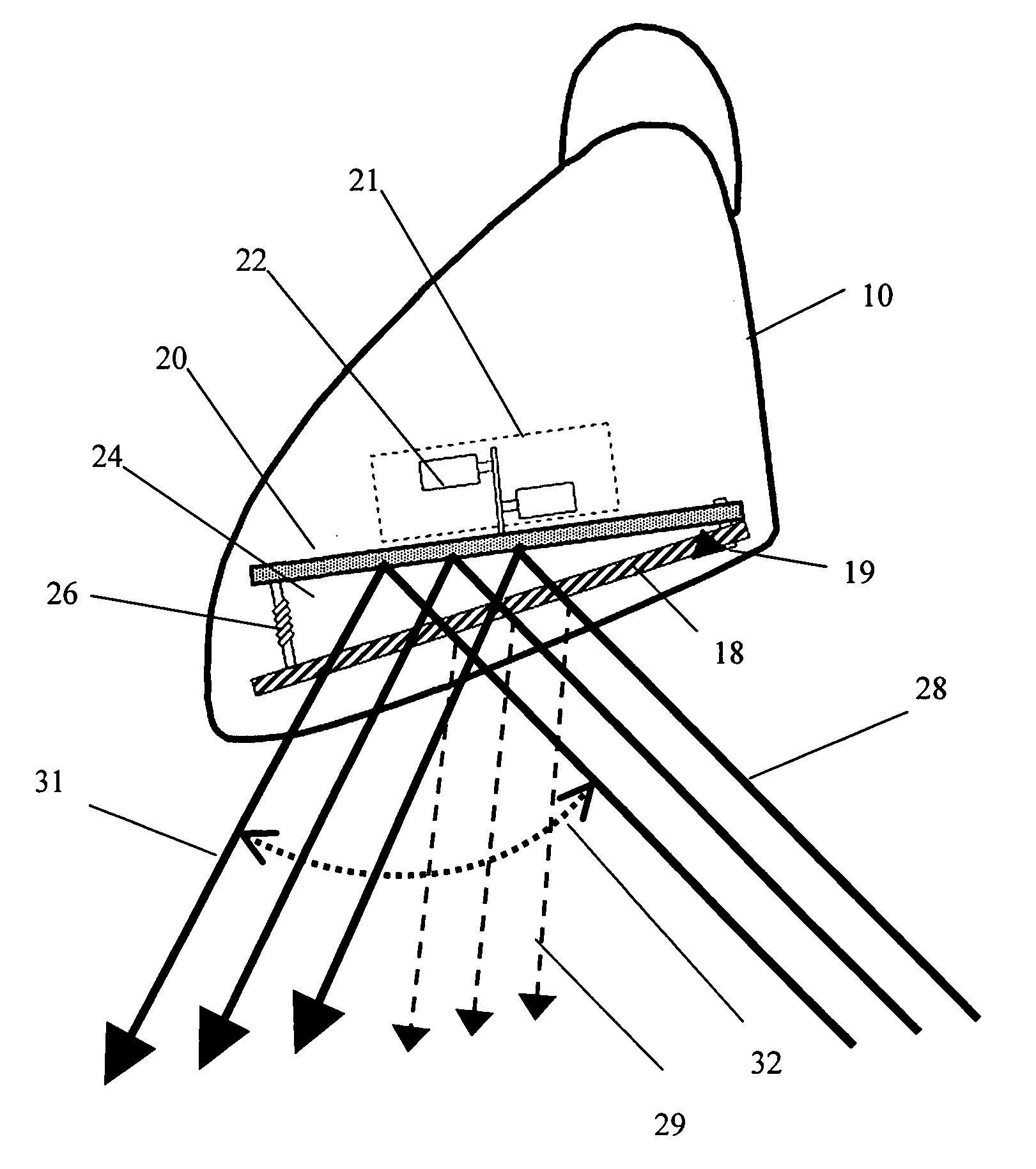
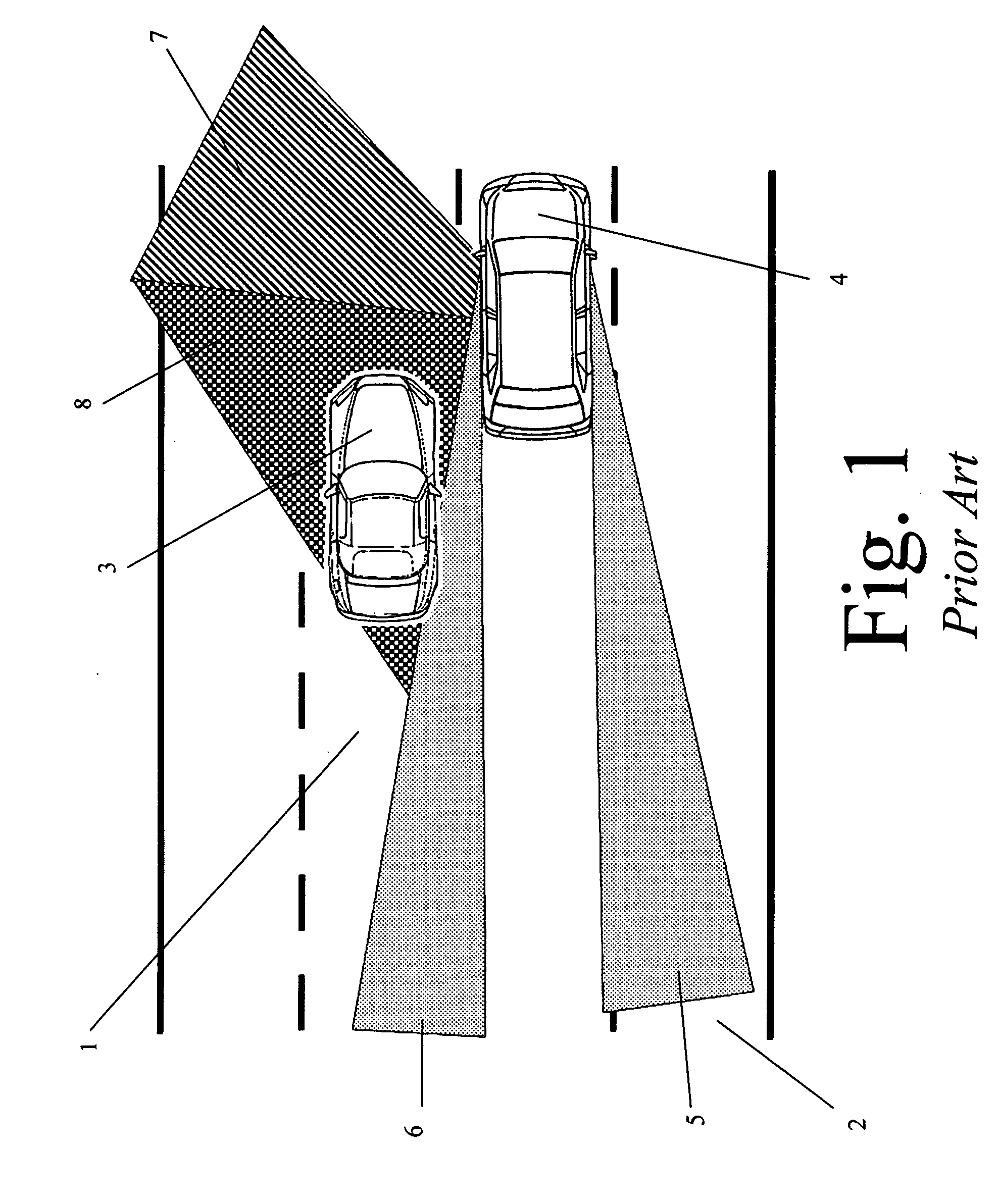
[0014] The present invention is a system that augments conventional power side mirror designs and is capable of reflecting a wider side view of the vehicle to the driver based on either driver activation or passive activation when coupled with an external sensory system. Virtually all emerging blind spot detection systems known in the prior art rely on an electronic sensing or detection mechanism to alert the driver when an object has entered his / her blind spot zone. Conversely, the present invention is a blind spot exposure system that exposes the blind spot zone to the driver using a familiar, ergonomically-accepted interface: the vehicle's side mirror. With the present invention, the driver is empowered to make informed driving decisions based on his / her own assessment of the exposed contents of the blind spot zone.
[0016] Upon application of voltage, the electrochromatic mirror surface becomes transparent thereby exposing a second, conventional mirror surface positioned and offset behind it. As the conventional mirror surface is offset by a specific angle, for example +4 to +24 degrees, depending on the vehicle geometry and a number of additional factors, the angle of reflection of the driver's view is increased by the offset angle of the conventional mirror's surface to that of the electrochromatic mirror surface. This increase in the angle of reflection exposes a wider angle of the space next to and behind the vehicle, thereby exposing the vehicle's blind spot zone to the driver.
[0022] A variable time interval based on the vehicle's speed. Through continuous acquisition of the vehicle's speed, the circuit can determine the appropriate duration of blind spot exposure to ensure greater responsiveness to the driver's real-time needs. i.e. the faster the vehicle, the shorter the blind spot exposure interval shall be.
[0027] The auto-dimming property is actuated through continuous input from the optional photocell attached to the electrochromatic mirror surface and facing the rear of the vehicle either at the same angle of reflection as the electrochromatic mirror surface or at a slightly greater angle (outwardly facing away from the vehicle). The photocell sends a signal that describes the luminescence of the incident light beams on the electrochromatic mirror surface. The circuit logic (in the digital microcontroller) in turn interprets the photocell's signal and calculates a level of partial voltage application to the electrochromatic mirror surface. The partial voltage renders the electrochromatic mirror surface variably translucent wherein a certain percentage of light rays are absorbed through the electrochromatic mirror surface rather than reflected. This process accomplishes an anti-glare, auto-dimming function for side mirrors.
[0028] It is therefore an object of the present invention to produce a blind spot exposure state that is automated in response to a single driver engagement or the output of an external sensor, provides for blind spot exposure, then returns to its normal operating state that is readily adaptable for implementation in any motor vehicle.

Problems solved by technology

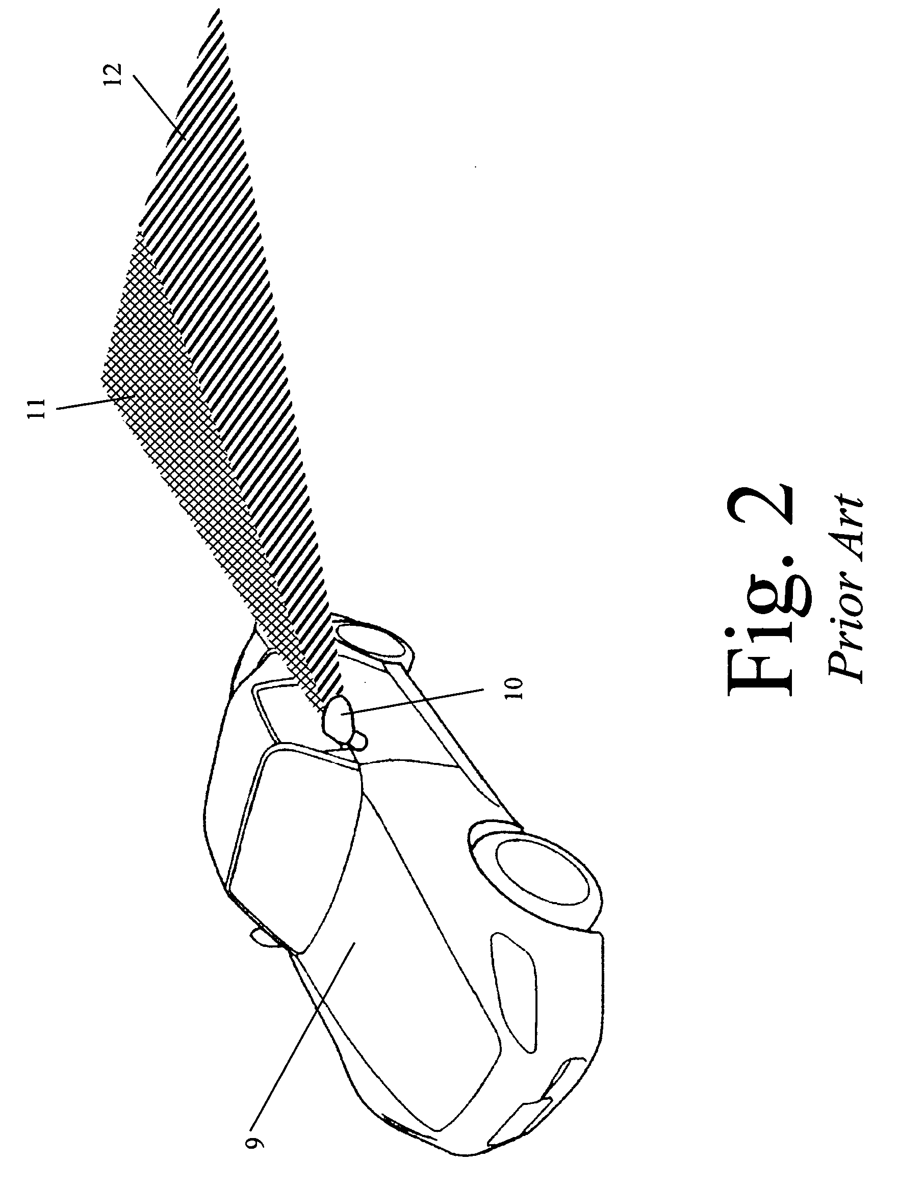
These side mirrors are based on a design that is incapable of displaying, or “detecting”, a vehicle occupying a directly adjacent lane and approaching the reference vehicle from the rear such as the situation of a faster vehicle passing a slower vehicle.
Such manual techniques to the persistent blind spot problem are inherently flawed and posses several shortcomings.
Driver fatigue or low alertness levels often contribute to ignoring or neglecting to perform this manual check when changing lanes.
Another well-known problem in the prior art is that vehicle designs vary widely.
Some vehicles have severely restricted side view through and behind the driver side B-pillar.
Similarly, tall SUVs, while having ample viewing room up to the B-pillar on the driver side, have impeded blind spot view due to their relatively large dimensions, including height.
In essence, any B-pillar or height design issues inherently limit the side and rearward view through the driver's side window.
This consequently further limits the reliability and efficiency of conventional blind spot checking mechanisms known in the prior art in preventing avoidable lane change collisions.
For the foregoing reasons, conventional blind spot detection systems known in the prior do not have sufficient means for providing significant benefits in collision avoidance.

Method used


Image

  • Electrochromatic polymer mirror surface for vehicle blind spot exposure
  • Electrochromatic polymer mirror surface for vehicle blind spot exposure
  • Electrochromatic polymer mirror surface for vehicle blind spot exposure

Examples


Embodiment Construction

[0039] In the following detailed description of the invention of exemplary embodiments of the invention, reference is made to the accompanying drawings (where like numbers represent like elements), which form a part hereof, and in which is shown by way of illustration specific exemplary embodiments in which the invention may be practiced. These embodiments are described in sufficient detail to enable those skilled in the pertinent arts to practice the invention, but other embodiments may be utilized and logical, mechanical, electrical, and other changes may be made without departing from the scope of the present invention. The following detailed description is therefore, not to be taken in a limiting sense, and the scope of the present invention is defined only by the appended claims.

[0040] In the following description, numerous specific details are set forth to provide a thorough understanding of the invention. However, it is understood that the invention may be practiced without ...


PUM


Abstract

The present invention teaches the use of a blind spot exposure system comprised of two consecutive reflective mirror surfaces. The first mirror surface is formed of an electrochromatic polymer while the second reflective surface is composed of conventional reflective mirror glass. The two surfaces are positioned such as the first electrochromatic reflective surface forms the reflected view in the vehicle's side mirror during the system's normal operating state. Once the system is activated electrical voltage is applied to the electrochromatic first surface rendering it transparent thereby uncovering the conventional reflective mirror surface behind it which is offset by a fixed blind spot exposure angle that may range between +4 degrees and +24 degrees. The present invention also teaches of a number of alternative embodiments including: an anti-glare automatic dimming mode based on the use of an optional external light sensor, the integration with a vehicle's turn signals or external sensors as means of activating the blind spot exposure state, the ability to produce a speed sensitive mode in which the system engages in blind spot exposure mode for a shorter period of time at higher vehicular speeds; and the use of LED indicators to provide visual notification whenever the system in a given side mirror is in an expanded blind spot exposure state.

Description

CROSS REFERENCE TO RELATED APPLICATIONS [0001] This application claims priority from U.S. Provisional Patent Application Ser. No. 60 / 653,344, entitled “Electrochromatic Polymer Mirror Surface for Vehicle Blind Spot Exposure”, filed on Jan. 16, 2005.FEDERALLY SPONSORED RESEARCH [0002] Not Applicable SEQUENCE LISTING OR PROGRAM [0003] Not Applicable TECHNICAL FIELD OF THE INVENTION [0004] The present invention relates generally to a controlled mirror system that temporarily alters the reflective angle of mirror surface to reflect an alternative viewing angle. More specifically the present invention teaches the use of an electrochromatic automotive side mirror surface that, upon driver's demand or based on sensor input, widens its angle of reflection of the side mirror(s) thereby exposing the contents of the vehicle's blind spot. BACKGROUND OF THE INVENTION [0005] Motor vehicles rely on two mirrors mounted on each side of the vehicle to uncover objects, including other vehicles such as...

Claims


Application Information

Patent Timeline
IPC IPC(8): G02F1/15
CPCB60R1/025B60R1/081
Inventor MALHAS, KHALED
Owner MALHAS KHALED
Learn More