Apparatus for blow molding

Inactive Publication Date: 2006-08-17
UNILOY MILACRON USA INC
View PDF12 Cites 5 Cited by
  • Summary
  • Abstract
  • Description
  • Claims
  • Application Information

AI Technical Summary

Benefits of technology

[0010] In accordance with the aforesaid objects the present invention provides a molding tool for molding a substantially hollow article from a tubular parison, the molding tool comprising first molding surfaces defining a primary cavity for forming a hollow body portion of a molded article, the body portion having walls formed by expansion of the parison within the primary cavity, and second molding surfaces defining at least one first solid area of the article to be molded attache

Problems solved by technology

This increased thermal mass increases the time required to transfer sufficient heat from the material to attain the desired rigidity, increasing the overall time required to complete a molding cycle.
As a consequence, known molding tools for

Method used


Image

  • Apparatus for blow molding
  • Apparatus for blow molding
  • Apparatus for blow molding

Examples


Embodiment Construction

[0015] The invention shall be illustrated with reference to a preferred embodiment which shall be described in detail. It is not the intention of applicant that the invention be limited to the preferred embodiment, but rather that the invention shall be defined by the appended claims and all equivalents thereof.

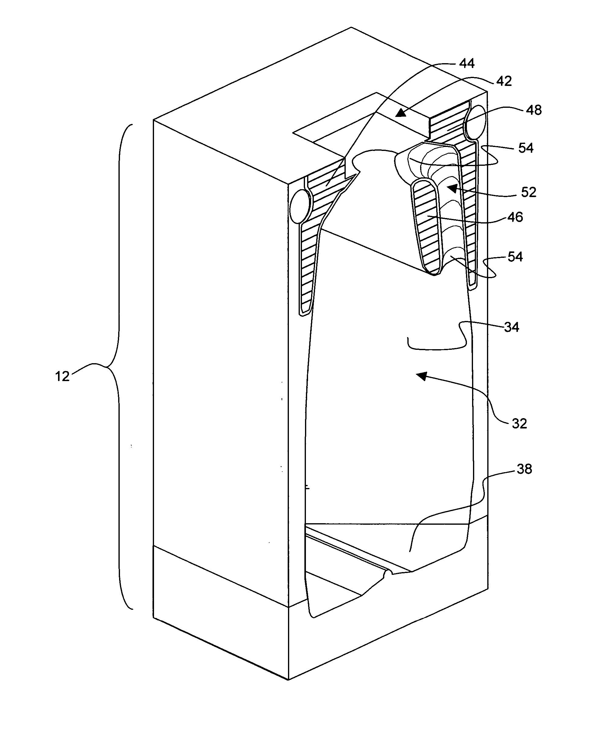
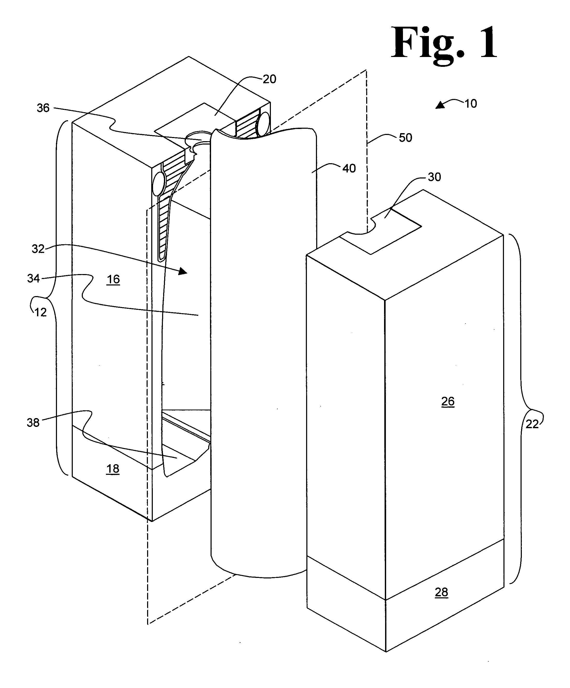
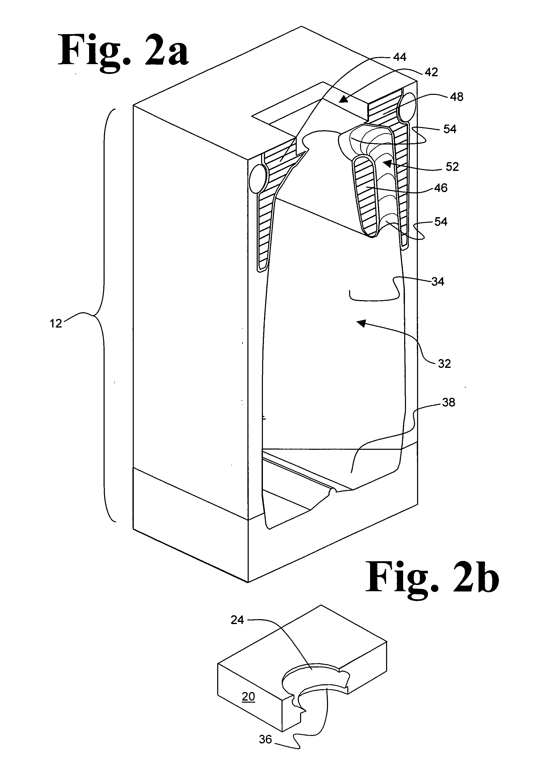
[0016] Referring to FIG. 1, mold assembly 10 comprises mating mold components 12 and 22 each referred to herein as a “mold half” or “molding tool”. Each of mold components 12 and 22 is carried by a member of a molding machine press (not shown) for translating the mold components between open and closed positions relative to each other (the open position depicted in FIG. 1). In the open position, mold components 12 and 22 are separated permitting admission of a parison such as parison 40 therebetween and removal of a molded article upon completion of a molding operation. In the closed position, mold components 12 and 22 abut at parting plane 50, the abutting faces of mold com...


PUM

PropertyMeasurementUnit
Timeaaaaaaaaaa
Areaaaaaaaaaaa
Heataaaaaaaaaa

Abstract

A molding tool for molding a substantially hollow article from a tubular parison comprises molding surfaces defining at least one cavity for forming a hollow portion of a molded article, the hollow portions having walls formed by expansion of the parison within the cavities and defining at least one solid area of the article to be molded attached to a wall of a hollow portion, the solid area comprising waste of the article as molded and the molding surfaces comprising surface undulations effective to improve the rate of heat transfer between the molding surfaces and the molding material comprising the solid areas. A mold assembly for molding hollow articles from tubular parisons comprises a molding tool in accordance with the invention. A blow molding machine comprises a mold assembly in accordance with the invention.

Description

I. BACKGROUND OF THE INVENTION [0001] 1. Field of the Invention [0002] This invention relates generally to blow molding. In particular, this invention relates to tooling for blow molding. [0003] 2. Description of Related Art [0004] Blow molding is a cyclic process wherein a parison of material in a moldable condition is centered on the parting plane of a mold assembly, the mold assembly is closed around the parison, the parison is expanded so the exterior of the parison abuts molding surfaces defining a molding cavity of the closed mold assembly, the blow molded article is conditioned to be sufficiently rigid to retain its size and shape while unsupported, the mold assembly is opened and the blow molded article is removed. In general, the moldable condition of the parison is achieved when the material of the parison is at an elevated temperature, and the rigid condition of the blow molded article is achieved when the temperature of the material has been reduced. A blow molding machi...

Claims


Application Information

Patent Timeline
IPC IPC(8): B29C49/64
CPCB29C49/04B29C49/4802B29C2049/4805B29C2049/4853B29C2049/4887B29L2031/463
Inventor RODRIGUEZ, RICKPADLEY, ROBERT L. JR.MADDOX, A. DALE
Owner UNILOY MILACRON USA INC
Why Eureka
Try Eureka