Turbine moving blade internal composite cooling structure

A composite cooling and moving blade technology, applied in engine components, engine functions, machines/engines, etc., can solve problems such as difficult to achieve cooling effect, and achieve the effect of enhancing fluid turbulent kinetic energy, improving heat transfer level, and reducing resistance loss

Active Publication Date: 2021-08-17
XI AN JIAOTONG UNIV
View PDF7 Cites 0 Cited by
  • Summary
  • Abstract
  • Description
  • Claims
  • Application Information

AI Technical Summary

Problems solved by technology

It is difficult to achieve the expected cooling effect by using a single cooling structure. Therefore, it is necessary to combine different cooling structures and give full play to the advantages of various cooling structures to further improve the enhanced heat transfer capacity of the internal cooling channel and adapt to the new generation of combustion gas. machine development

Method used


Image

  • Turbine moving blade internal composite cooling structure
  • Turbine moving blade internal composite cooling structure
  • Turbine moving blade internal composite cooling structure

Examples


Embodiment Construction

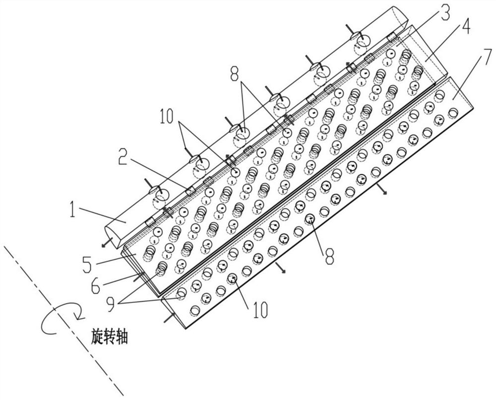
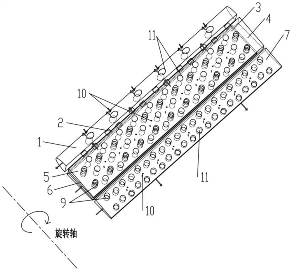
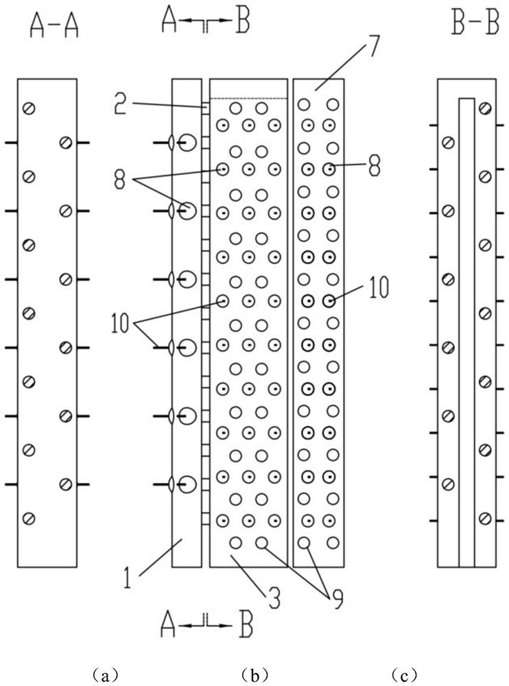
[0036] The present invention will be further described below in conjunction with accompanying drawing:

[0037] refer to Figure 1 to Figure 6 , a composite cooling structure inside a turbine blade provided by the present invention, comprising a swirl cooling channel 1, a U-shaped cooling channel 3 and a trailing edge trapezoidal cooling channel 7, a U-shaped cooling channel inlet section 5 of the U-shaped cooling channel 3 and The outlet section 6 of the U-shaped cooling channel communicates with the swirl cooling channel 1 through several jet holes 2 . The swirling flow cooling channel 1, the U-shaped cooling channel 3 and the trailing edge trapezoidal cooling channel 7 are arranged on the surface with a number of ball sockets 8 / ball convexes 11 and air film holes 10 structures, and the U-shaped cooling channel 3 and the trailing edge trapezoidal cooling channel 7 are arranged There are several fin 9 structures.

[0038] refer to Figure 3 to Figure 6, the shape of the ta...


PUM


Abstract

The invention discloses a turbine moving blade internal composite cooling structure. The turbine moving blade internal composite cooling structure comprises a leading edge rotational flow cooling passage, a middle chord U-shaped cooling passage and a tail edge trapezoidal cooling passage, wherein the U-shaped cooling passage comprises a U-shaped cooling passage inlet section, a U-shaped cooling passage outlet section and a U-shaped cooling passage top turning area which are integrally formed, wherein the U-shaped cooling passage inlet section and the U-shaped cooling passage outlet section communicate through the U-shaped cooling passage top turning area, and the U-shaped cooling passage inlet section, the U-shaped cooling passage outlet section and the rotational flow cooling passage communicate through a plurality of jet flow holes which are formed in a staggered mode; a plurality of ball sockets/ball protrusions and air film hole structures are arranged on the surface of the whole cooling passage; and a plurality of fin structures are arranged in the U-shaped cooling passage and the tail edge trapezoidal cooling passage. According to the turbine moving blade internal composite cooling structure, through coupling of multiple structures, the structural strength of the blade is guaranteed, and the advantages of high heat transfer, low resistance, high adaptability and the like are achieved.

Description

technical field [0001] The invention belongs to the technical field of turbine cooling, in particular to a composite cooling structure inside a turbine moving blade. Background technique [0002] Gas turbine is a very important energy power equipment, which is widely used in energy, electric power, aerospace, aviation, ships, military and other fields. It is a major equipment of strategic significance for national defense and energy power industry. The technical development level of jet engines and heavy-duty gas turbines is an important symbol to measure the strength of a country's manufacturing industry. Therefore, carrying out research on key technologies of gas turbines and developing gas turbines with independent intellectual property rights in my country is crucial to my country's national economic development, energy security and national defense security. are of great significance. [0003] The improvement of gas turbine power and efficiency depends largely on the co...

Claims


Application Information

Patent Timeline
Patent Type & Authority Applications(China)
IPC IPC(8): F01D5/18
CPCF01D5/18F01D5/187F01D5/186F05D2260/22141F05D2260/2212Y02T50/60
Inventor 张荻高同心景祺谢永慧
Owner XI AN JIAOTONG UNIV
Why Eureka
Try Eureka