Lighting arrangement having a resilient element

Active Publication Date: 2016-08-04
SIGNIFY HOLDING B V
View PDF0 Cites 0 Cited by
  • Summary
  • Abstract
  • Description
  • Claims
  • Application Information

AI Technical Summary

Benefits of technology

[0014]The carrier can be a heat sink in thermal contact with the circuit board. The transfer of heat away from the circuit board can be improved by the resilient element pressing the circuit board against the heat sink on which the circuit board is arranged.
[0015]The lighting arrangement can have at least one light source mounted on each of two opposing sides of the circuit board. Arranging the light sources to emit light from two sides of the circuit board can be advantageous in some applications.
[0016]The carrier can have a reflective layer for reflecting light emitted by the light sources and two recesses facing the reflective layer so that the reflective layer can be received by the two recesses when the resilient element presses against the circuit board. A reflective layer may increase the illumination efficiency of the ligh

Problems solved by technology

This, in turn, can reduce the risk of the circuit board, and hence also the light sources, moving, or disp

Method used


Image

  • Lighting arrangement having a resilient element
  • Lighting arrangement having a resilient element
  • Lighting arrangement having a resilient element

Examples


Example

[0026]The figures are provided to illustrate the general structures of embodiments of the present invention. As illustrated in the figures, the sizes of certain features can be exaggerated for illustrative purposes. Like reference numerals refer to like elements throughout.

DETAILED DESCRIPTION

[0027]The present invention will now be described more fully hereinafter with reference to the accompanying drawings, in which currently preferred embodiments of the invention are shown. This invention may, however, be embodied in many different forms and should not be construed as limited to the embodiments set forth herein; rather, these embodiments are provided for thoroughness and completeness, and fully convey the scope of the invention to the skilled person.

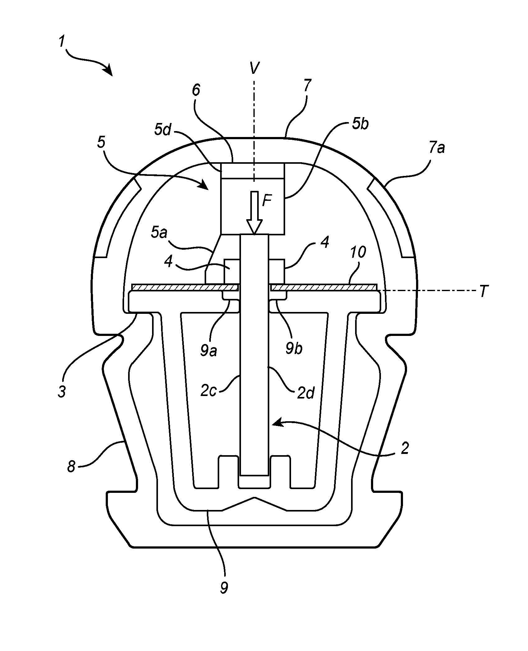
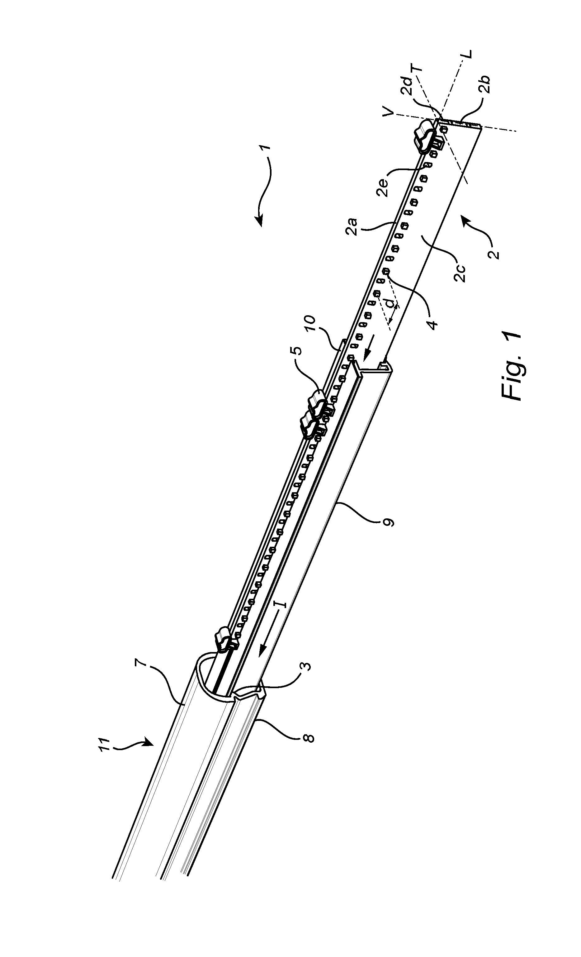
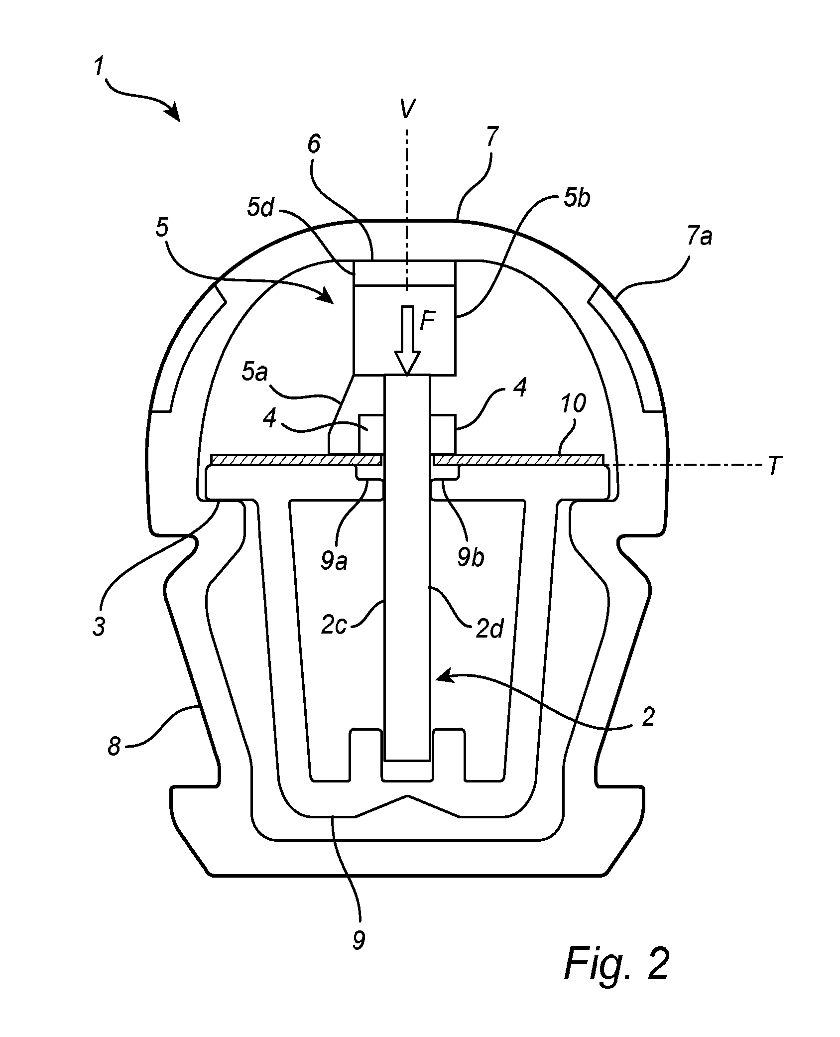
[0028]A lighting arrangement 1 in the form of a straight tube lighting system is described below with reference to FIGS. 1 to 3. A transverse cross-sectional view of the tube lighting system 1 in FIG. 1 is shown in FIG. 2. A schematic ...


PUM


Abstract

A lighting arrangement (1)is disclosed. The lighting arrangement (1)has a circuit board (2),a support (3) for supporting the circuit board (2) and at least one light source (4) mounted on the circuit board(2). The lighting arrangement also has at least one abutment (6) which is fixed relative to the support (3) and at least one resilient element (5) which is sandwiched between the at least one abutment (6) and the circuit board (2), whereby the resilient element (5) presses against the circuit board (2).

Description

FIELD OF THE INVENTION[0001]The present disclosure relates to lighting arrangements, such as tube lighting systems.BACKGROUND OF THE INVENTION[0002]Many different types of lighting arrangements are known in the art and used for a variety of purposes. Typical applications include illumination of interior spaces, architectural lighting and automotive lighting.[0003]A common type of lighting arrangements is tube lighting systems having light-emitting diodes (LEDs) mounted on a printed circuit board (PCB) inside a straight tubular housing. Various mechanisms for maintaining the PCB in position inside the tubular housing are used. An example of such a mechanism is two opposing slots, provided on the inside of the tubular housing, into which the PCB is inserted. The slots are usually designed to provide a small clearance space for facilitating the insertion of the PCB. This mechanism is typically found in tube lighting systems having a one-piece tubular housing. In some tube lighting syst...

Claims


Application Information

Patent Timeline
IPC IPC(8): F21V19/00F21V29/70F21K99/00
CPCF21V19/004F21V29/70F21K9/27F21Y2103/003F21Y2101/02F21Y2115/10F21Y2101/00F21K99/00
Inventor VAN GOMPEL, WALTHERUS EMERICUS JOHANNESVAN DUIJNEVELDT, WIDO
Owner SIGNIFY HOLDING B V
Why Eureka
Try Eureka