Premix burner

a burner and pre-mix technology, applied in the field of burners, can solve the problems of clearly increasing pollutant emissions, narrow stability and operating range, etc., and achieve the effect of preventing pulsation even more effectively and broader operating rang

Inactive Publication Date: 2006-08-17
ANSALDO ENERGIA IP UK LTD
View PDF1 Cites 27 Cited by
  • Summary
  • Abstract
  • Description
  • Claims
  • Application Information

AI Technical Summary

Benefits of technology

[0012] The advantages of the invention are, among other things, that the fuel is optimally injected across the entire load range. The incremental injection via the lance and additional injection openings means that premix burners can now be used for a broader operating range. The operation of these premix burners with incremental fuel supply covers at least the entire operating range of conventional pilot / premix burners.
[0013] In addition, asymmetric fuel injection can prevent pulsation even more effectively. The asymmetry refers to pairs of injection openings that are arranged opposite each other in flow direction and the injection openings on the lance. The asymmetry can be static by not arranging an injection opening across the area opposite an injection opening. This can also be achieved by individually controlling the fuel supply to the symmetrical fuel injection openings or by turning the lance. Using the control mechanism, opposite fuel injection openings then receive different amounts of fuel and, depending on the load point or starting or shutdown conditions, a symmetrical or asymmetrical fuel profile is obtained in the cone cavity of the vortex generator.

Problems solved by technology

Premix burners that are operated based on the concept of lean premix combustion, have low pollutant emissions but also a clearly restricted stability and operating range.
However, already small amounts of 10% pilot gas, for example, can result in clearly increased pollutant emissions since the pilot flames work in diffusion operation.

Method used


Image

  • Premix burner
  • Premix burner
  • Premix burner

Examples


Embodiment Construction

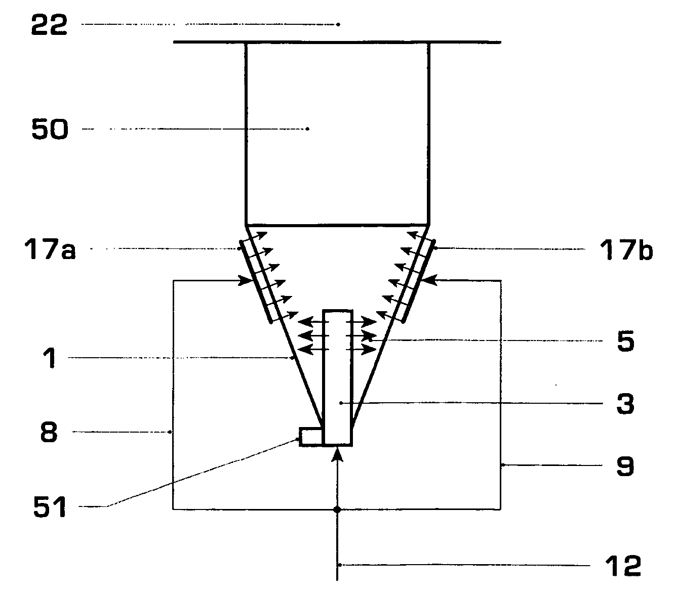
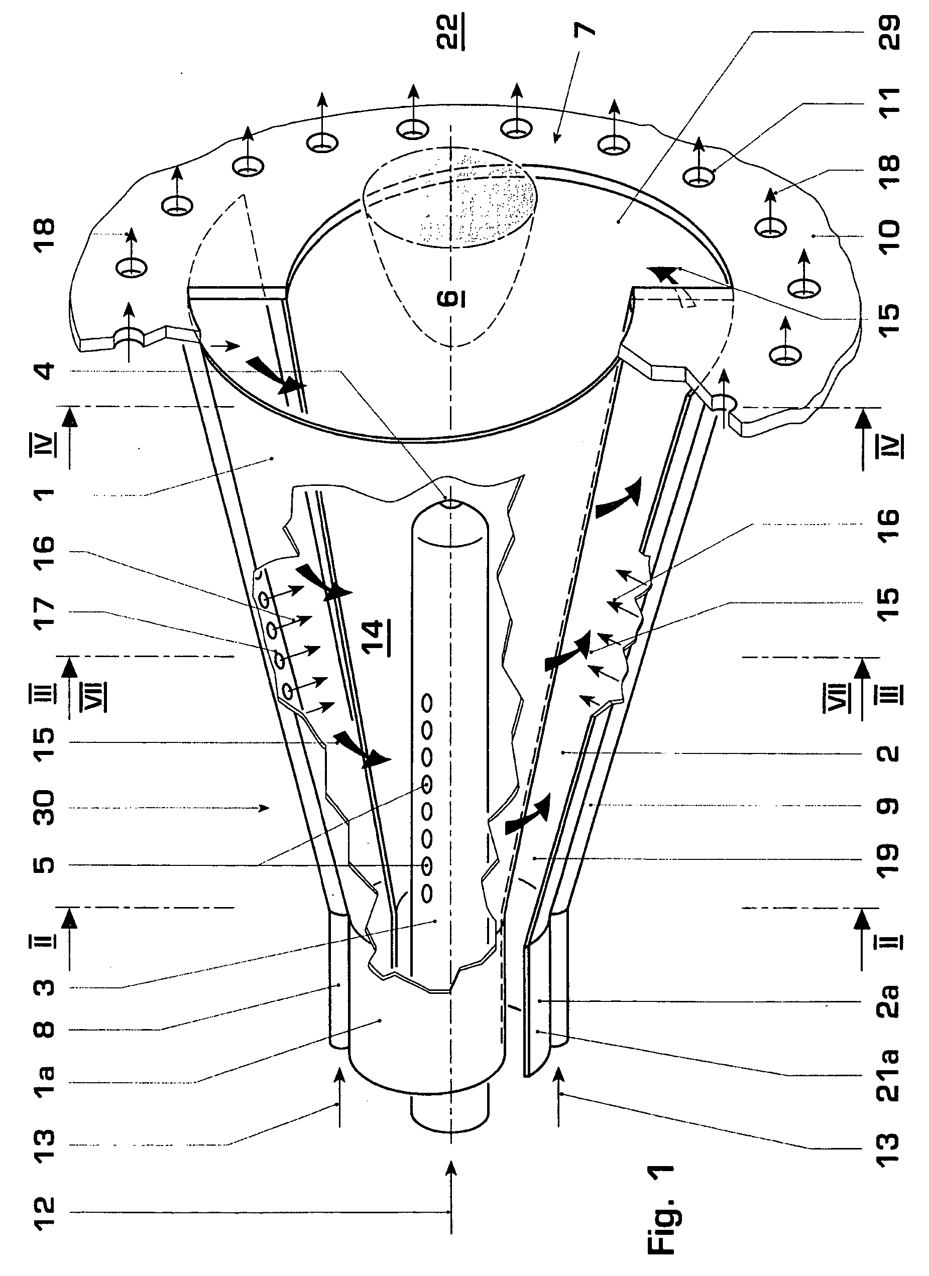
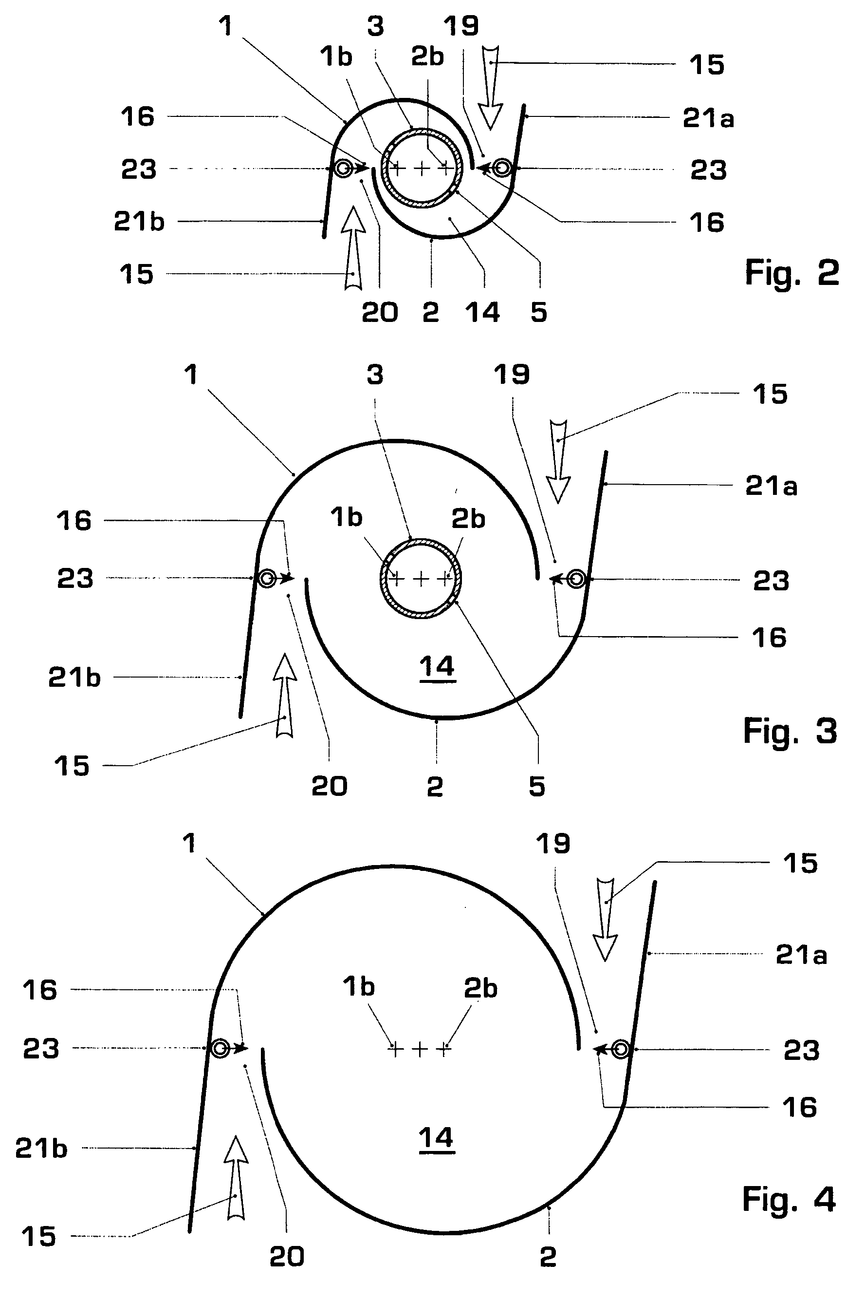
[0027] The burner according to FIG. 1 includes a vortex generator 30 that mainly consists of two half, hollow conical body segments 1, 2, that are offset with regard to each other. Such a burner is called a double-cone burner. By offsetting the respective centerline 1b, 2b of the conical body segment 1, 2 with regard to each other one obtains a tangential air duct 19, 20, (FIG. 2-4) on both sides that are laterally reversed and through which the combustion air 15 flows into the interior space of the burner, i.e. into the cone cavity 14, also called vortex cavity. The two conical body segments 1, 2 have a cylindrical part 1a, 2a that also run offset with regard to each other analogously to the conical body segments 1, 2 so that the tangential air ducts 19, 20 are available from the start. A fuel lance 3 is arranged in this cylindrical segment 1a, 2a that extends into the cone cavity 14 downstream. Of course the burner can be cone-shaped, i.e. without a cylindrical segment 1a, 2a. Eac...


PUM


Abstract

A premix burner includes a vortex generator (30) for combustion air stream (15), devices (17, 17a, 17b, 31-38, 41-48) to inject fuel into the combustion air stream (15), and tangential air ducts (19, 20). The combustion air (15) enters the cone cavity (14) of the vortex generator (30) via the air ducts. The injection of the fuel into the combustion air is done asymmetrically by injection devices (17, 17a, 17b, 31-38, 41-48). At least one of the injection devices (5) is arranged on a fuel lance (3) that extends into the vortex chamber.

Description

[0001] This application claims priority under 35 U.S.C. § 119 to German patent application number 10 2004 049 491.6, filed 11 Oct. 2004, the entirety of which is incorporated by reference herein. BACKGROUND OF THE INVENTION [0002] 1. Field of the Invention [0003] The invention is based on a burner. [0004] 2. Brief Description of the Related Art [0005] Premix burners that are operated based on the concept of lean premix combustion, have low pollutant emissions but also a clearly restricted stability and operating range. These restrictions are caused by flashback into the mixing zone of the burner and lift-off and extinguishing of the premix flame as well as by thermo-acoustic oscillations. The stability range during conventional operation of a premix burner is expanded by using pilot injection that is especially used in the lower load range. However, already small amounts of 10% pilot gas, for example, can result in clearly increased pollutant emissions since the pilot flames work in...

Claims


Application Information

Patent Timeline
Patent Type & Authority Applications(United States)
IPC IPC(8): F23D14/62
CPCF23C2900/07002F23D17/002F23R3/286F23R2900/00014
Inventor BERNERO, STEFANOMATZ, CHRISTIAN JOERGZAJADATZ, MARTINPASCHEREIT, CHRISTIAN OLIVER
Owner ANSALDO ENERGIA IP UK LTD
Why Eureka
Try Eureka