
Cellular telephone with remote video scope and motion detector

a technology of video scope and cellular telephone, which is applied in the field of remote video input, can solve the problems of not yet being used in the field of cellular telephone with remote video scope and motion detector, and achieve the effect of simple use of the devi

Inactive Publication Date: 2006-08-17
HAVIV YEHUDA
View PDF0 Cites 64 Cited by
  • Summary
  • Abstract
  • Description
  • Claims
  • Application Information

AI Technical Summary

Benefits of technology

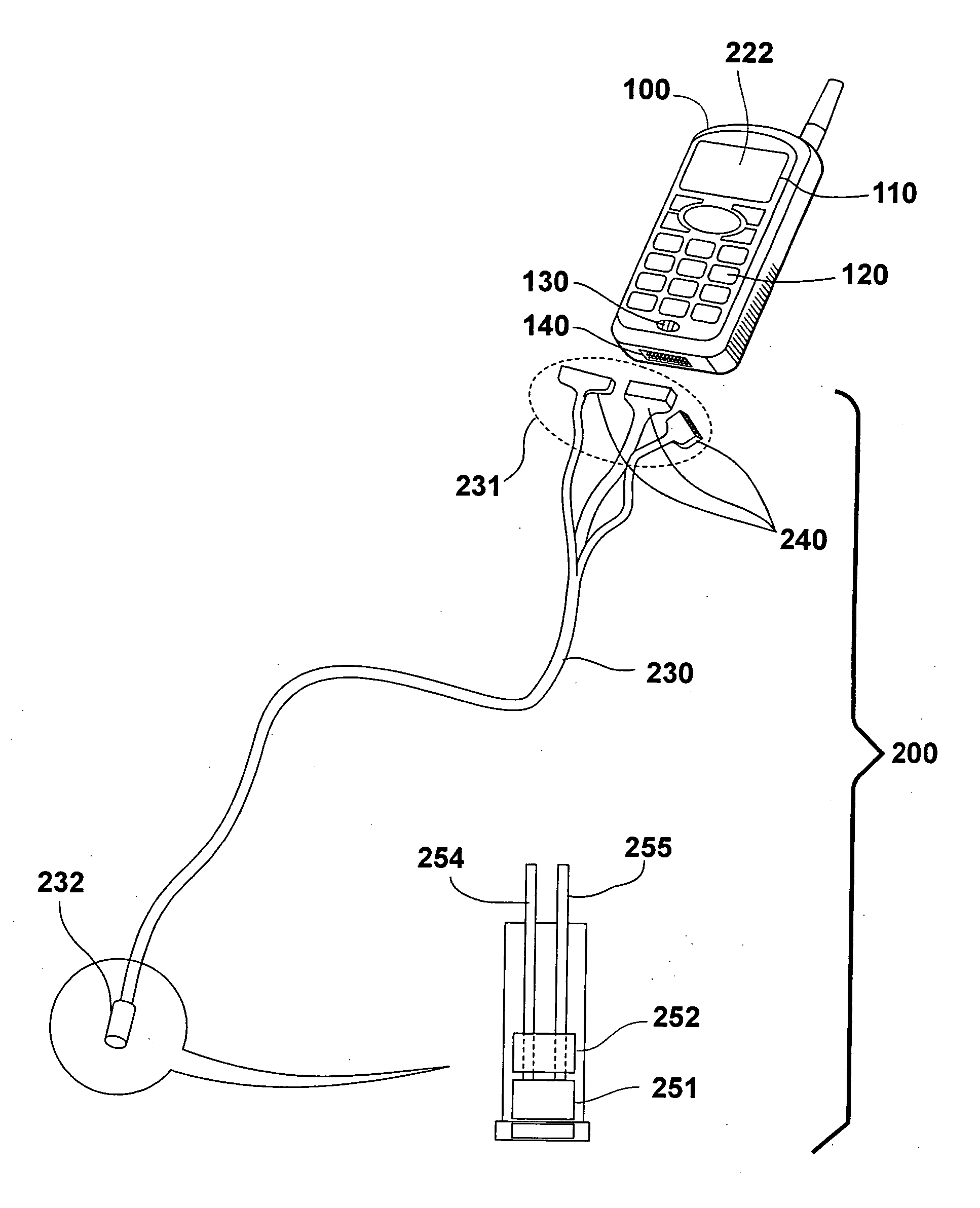
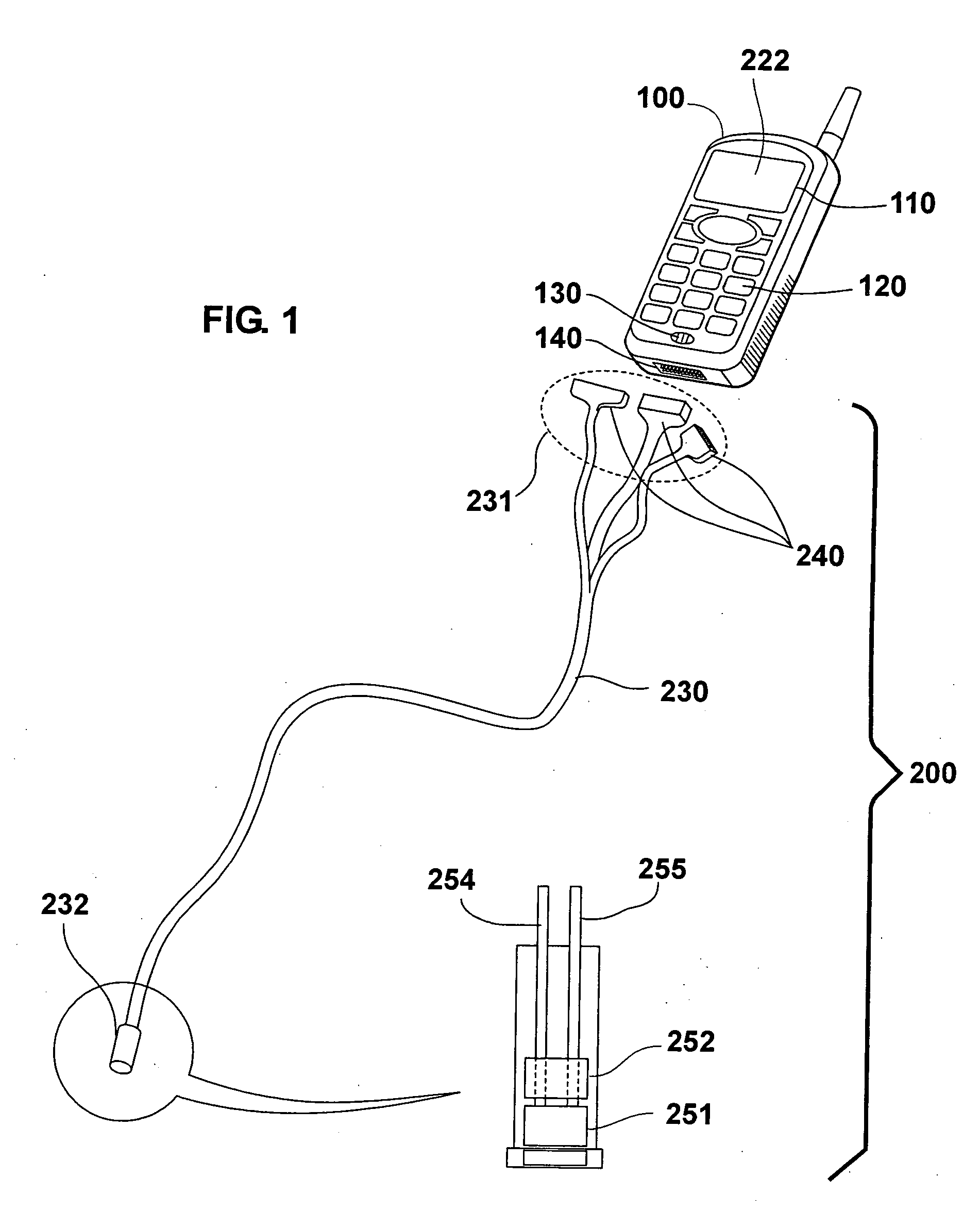
[0016] According to a further embodiment of the remote video data input aspect of the present invention, there is provided a flexible multi-lumenal sheath removably and slidably fitting one of its lumena over the exterior of the video scope apparatus from the distal end of the proximal video connector to the most distal aspect of the video scope apparatus for the purpose of allowing the transmission of the video scope apparatus and instruments and objects through the remaining lumena to and from the respective proximal and distal ends of the lumena.
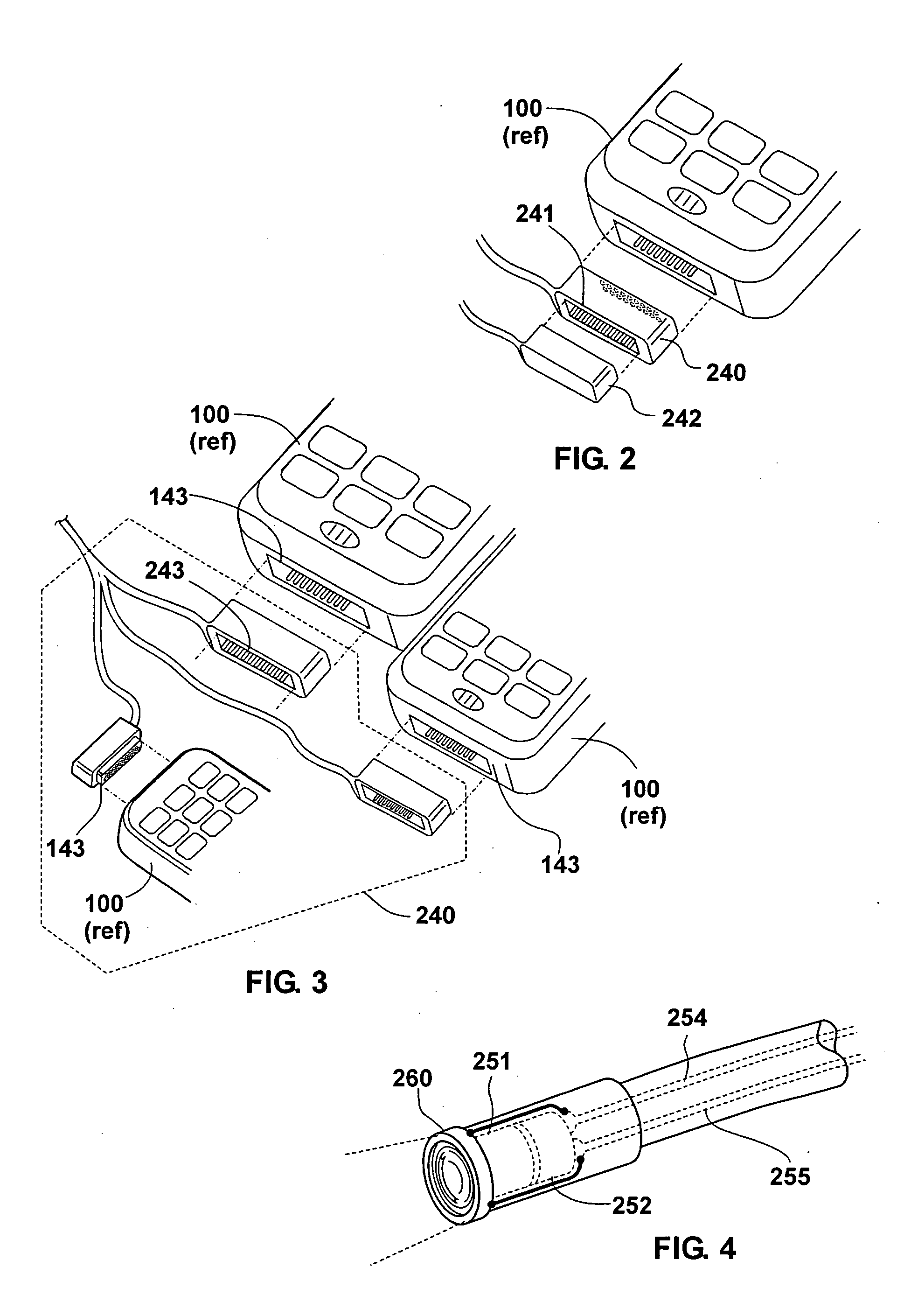
[0023] The use of the device is simple. The remote video apparatus is connected to the input / output port of the cellular telephone and the image sensed by the remote video apparatus is viewed on the display screen of the cellular telephone. This image may also be displayed on the display screen of other devices capable of receiving such images as digital transmission over cellular and physical transmission mechanisms. Using the pass-through connectors, the motion detector apparatus simultaneously may be attached to the same cellular telephone. The cellular telephone is configured to react to motion sensed by the motion detector apparatus by dialing a designated number, reporting the detection of motion, transmitting video data if it is available, and responding to instructions from the receiving unit. When motion is sensed by the motion detector apparatus, the cellular telephone dials the designated number, transmits the motion alarm and the available video data and corresponds with the receiver for further actions.

Problems solved by technology

The use of a cellular telephone with a remote video scope and a motion detector as one device, however, has not yet been practiced.

Method used


Image

  • Cellular telephone with remote video scope and motion detector
  • Cellular telephone with remote video scope and motion detector
  • Cellular telephone with remote video scope and motion detector

Examples


Embodiment Construction

[0035] The present invention is of a cellular telephone adapted with a removable video scope and a removable motion detector, which can be used collectively for a variety of functionality. Specifically, the present invention can be used to monitor a location via a cellular telephone and to advise a user when motion is detected in the monitored location. The present invention can also be used to view otherwise inaccessible places using the cellular telephone display device, transmit the same image of the cellular telephone and control the positioning of the video scope using the cellular telephone keypad or cellular telephone transmission.

[0036] The principles and operation of a video scope and motion detector attached to a cellular telephone according to the present invention may be better understood with reference to the drawings and the accompanying description.

[0037]FIG. 1 illustrates a basic embodiment of one aspect of the present invention, wherein there is provided a cellula...


PUM


Abstract

A cellular telephonic video scope and motion detector with the video scope and motion detector remotely and removably connected to the input / output port of the cellular telephone. A further embodiment allows control of the direction of the distal end of the video scope. A further embodiment allows attachment of the motion detector to the video scope. A further embodiment allows control of the video scope and motion detector via the cellular telephone keypad and cellular telephone transmission.

Description

FIELD AND BACKGROUND OF THE INVENTION [0001] The present invention relates to the combination of a cellular telephone, a video scope, and a motion detector. [0002] The use of endoscopic video cameras for various applications (predominantly medical uses) is well known in the art. The use of motion detectors for various applications (predominantly security related) is also well known in the art. The use of cellular telephony for various applications (predominantly communications) is also well known in the art. Video cameras and motion detectors have been used together in security-related applications. Cellular telephones with integrated video cameras have been used in the past. The use of a cellular telephone with a remote video scope and a motion detector as one device, however, has not yet been practiced. [0003] The object of the present invention is to combine the video, illumination, mobility, and grasping and manipulative features of a video scope and the motion detecting feature...

Claims


Application Information

Patent Timeline
IPC IPC(8): A61B1/00H04N7/18G16Z99/00
CPCH04N7/183A61B1/00043A61B1/0051A61B5/0013G16H40/67G16Z99/00A61B1/00042
Inventor HAVIV, YEHUDA
Owner HAVIV YEHUDA
Learn More