Ultrasonic endoscope device

a technology of endoscope and ultrasonic wave, which is applied in the field of ultrasonic endoscope, can solve the problems of difficult for an operator to understand which portion of the tube, the spatial positional relationship with the optical image is not grasped, and the endoscope is not ultrasoni

Inactive Publication Date: 2006-08-17
OLYMPUS CORP
View PDF10 Cites 122 Cited by
  • Summary
  • Abstract
  • Description
  • Claims
  • Application Information

AI Technical Summary

Problems solved by technology

Generally, an ultrasonic image of the ultrasonic endoscope has a problem that the spatial positional relationship with the optical image is not grasped.
Therefore, it is difficult for an operator to understand which portion of the tube cavity, as an ultrasonic image, is displayed on a monitor, and thus needs the skill for precise diagnosis using the ultrasonic image.
First, a scanned surface with ultrasonic waves is not viewed on the optical image.
Secondly, the scanned surface with ultrasonic waves is not always within the range of field-of-view of the optical image.

Method used


Image

  • Ultrasonic endoscope device
  • Ultrasonic endoscope device
  • Ultrasonic endoscope device

Examples


first embodiment

[0040] (First Embodiment)

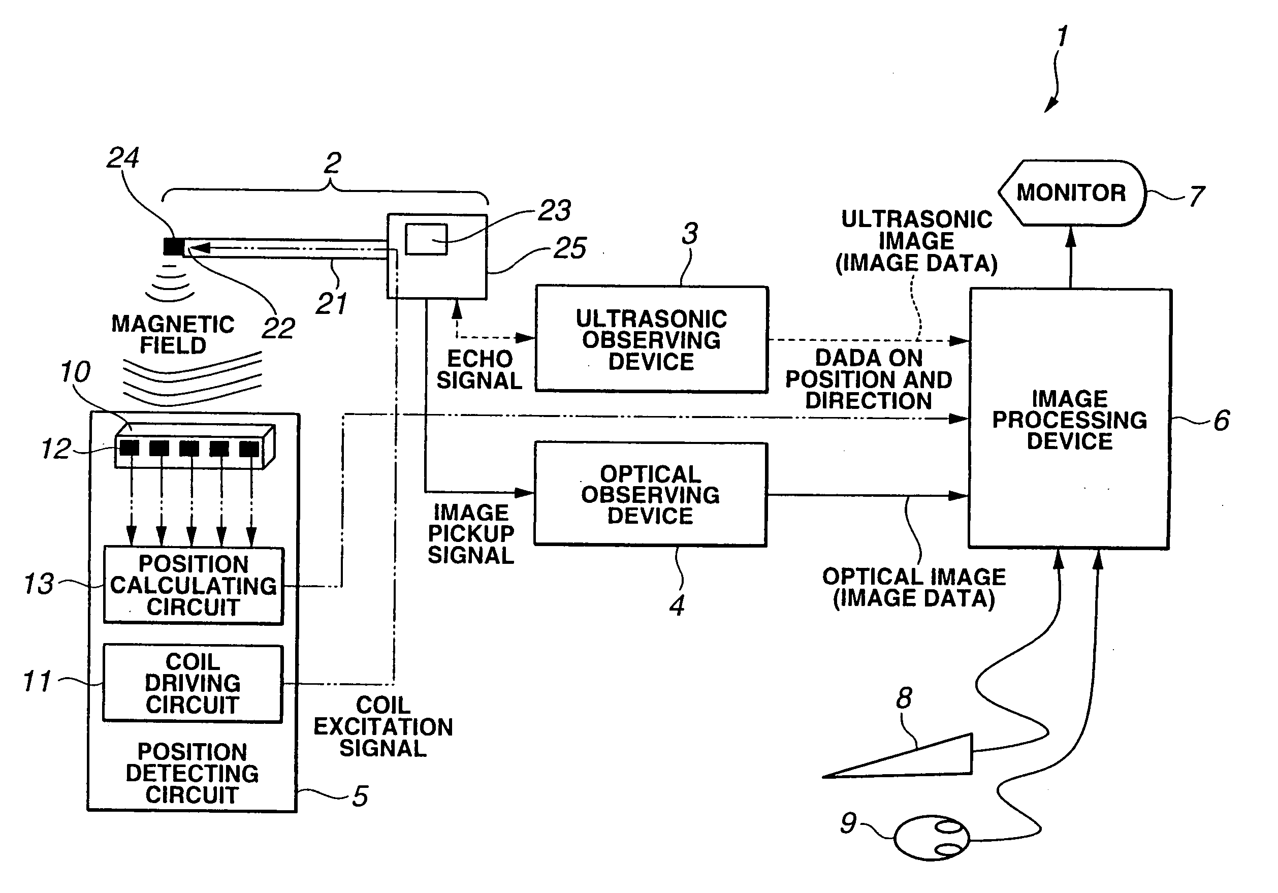
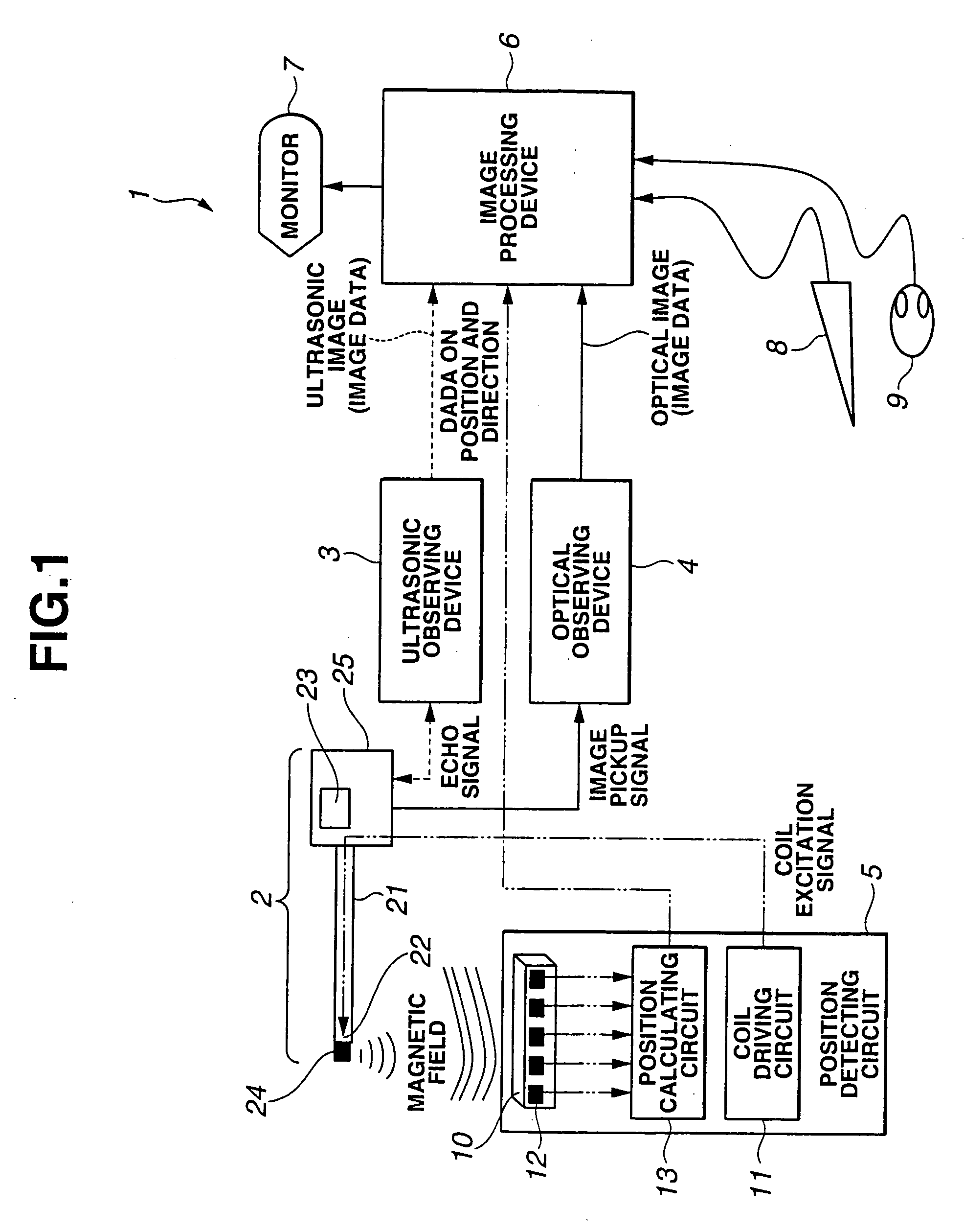
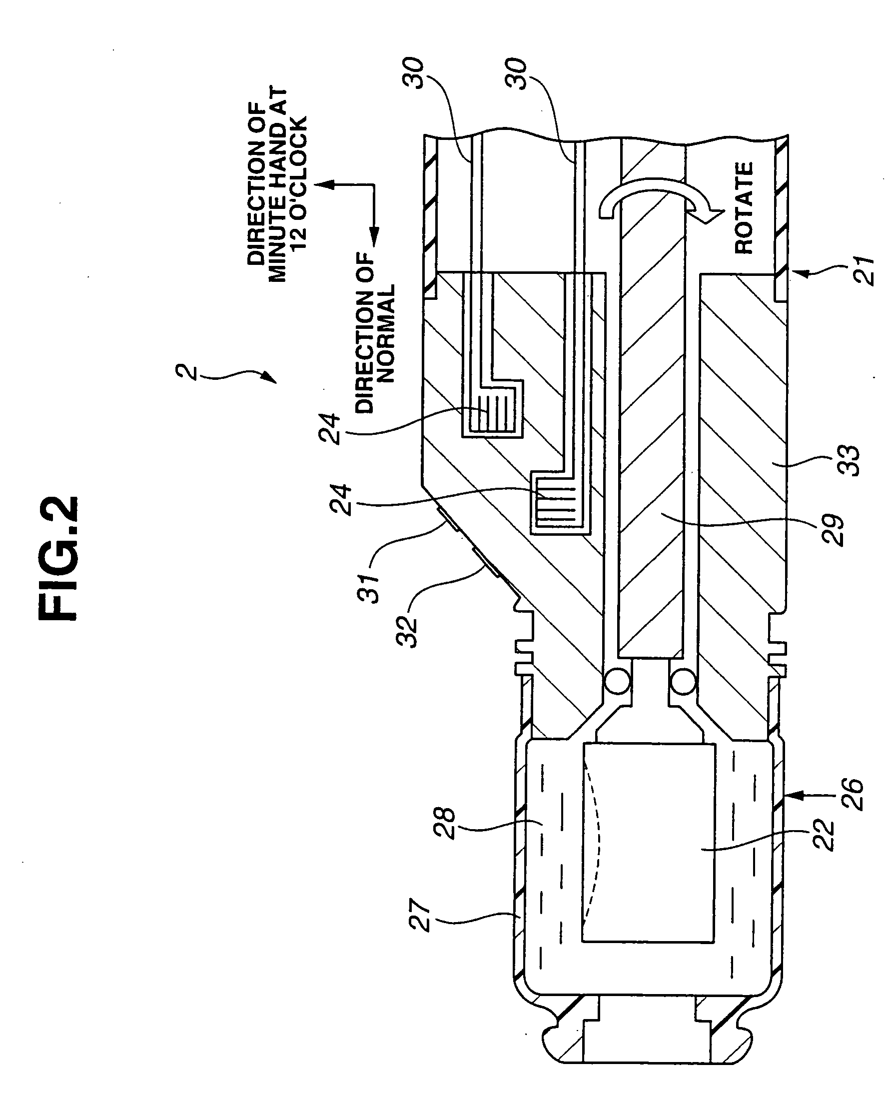
[0041] FIGS. 1 to 11 relate to a first embodiment of the present invention. FIG. 1 is a block diagram showing the overall configuration of an ultrasonic endoscope device. FIG. 2 is an enlarged cross-sectional view showing the distal end of the inserting side of an inserting portion of an endoscope. FIG. 3 is a block diagram showing an image processing device. FIG. 4 is a block diagram showing a shape matching circuit. FIG. 5 is an explanatory diagram of the operation of back-and-forth-by-hand scan. FIG. 6 is a conceptual diagram showing three-dimensional image data. FIG. 7 is an explanatory diagram of a re-cut-portion of three-dimensional image data. FIG. 8 is an explanatory diagram of surface shape data. FIG. 9 is an explanatory diagram of the image pickup operation of a target area with an endoscope. FIG. 10 is an explanatory diagram of the combination of an optical image and an ultrasonic image. FIG. 11 is an explanatory diagram of an image displayed on a...

second embodiment

[0131] (Second Embodiment)

[0132] Hereinbelow, a description is given of the structure and the operation of an ultrasonic endoscope device according to the second embodiment with reference to FIG. 15.

[0133]FIG. 15 is a block diagram showing a shape matching circuit according to the second embodiment of the present invention.

[0134] In the description of the second embodiment with reference to FIG. 15, the same components as those shown in FIGS. 1 to 11 according to the first embodiment are designated by the same reference numerals, and a description thereof is omitted.

[0135] (Structure)

[0136] Referring to FIG. 15, according to the second embodiment, the structure and operation of the shape matching circuit 110 are different from those according to the first embodiment.

[0137] The shape matching circuit 110 comprises: a surface shape memory 57; a surface shape memory 58; a gravity center calculating circuit 111 as gravity center calculating means; a gravity center comparing circuit...

third embodiment

[0157] (Third Embodiment)

[0158] Hereinbelow, a description is given of the structure and the operation of an ultrasonic endoscope device according to a third embodiment with reference to FIG. 16.

[0159]FIG. 16 is a block diagram showing a shape matching circuit according to the third embodiment of the present invention.

[0160] In the description of the third embodiment with reference to FIG. 16, the same components as those shown in FIG. 15 according to the second embodiment are designated by the same reference numerals, and a description thereof is omitted.

[0161] (Structure)

[0162] Referring to FIG. 16, according to the third embodiment, the structure and the operation of the shape matching circuit 120 are different from those according to the second embodiment. Only portions different from those according to the second embodiment will be described.

[0163] The shape matching circuit 120 additionally has an adjusting circuit 121.

[0164] Other structures according to the third embod...


PUM


Abstract

An ultrasonic endoscope device includes an optical image obtaining device that obtains an optical image of an examinee, an ultrasonic-image obtaining device that obtains an ultrasonic image of the examinee, a positional-information obtaining device that obtains positional information of the optical image obtaining device with respect to the examinee upon obtaining the optical image, and a matching circuit that matches up an optical image obtained from the optical image obtaining device with the ultrasonic image obtained from the ultrasonic-image obtaining device based on the positional information obtained by the positional-information obtaining device.

Description

CROSS REFERENCE TO RELATED APPLICATION [0001] This application is a continuation application of PCT / JP2004 / 008151 filed on Jun. 4, 2004 and claims benefit of Japanese Application No. 2003-162845 filed in Japan on Jun. 6, 2003, the entire contents of which are incorporated herein by this reference.BACKGROUND OF THE INVENTION [0002] 1. Field of the Invention [0003] The present invention relates to an ultrasonic endoscope device that obtains an optical image and an ultrasonic image of an examinee. [0004] 2. Description of the Related Art [0005] Conventionally, various ultrasonic endoscopes are put into the practical use to be inserted from the opening of a patient and scan the body cavity with ultrasonic waves. [0006] The ultrasonic endoscope generally comprises, at the distal end thereof, an ultrasonic vibrator that performs the scanning operation with ultrasonic waves and receives echoes, and an optical observing window that observes an optical image of the surface of the tube cavity...

Claims


Application Information

Patent Timeline
Patent Type & Authority Applications(United States)
IPC IPC(8): A61B5/05A61B6/00A61B8/00A61B5/06A61B8/12
CPCA61B5/06A61B8/12A61B8/4254A61B8/445A61B8/463A61B8/5238A61B8/4461A61B5/062
Inventor KAWASHIMA, TOMONAO
Owner OLYMPUS CORP
Why Eureka
Try Eureka