Annuloplasty chain

a technology of annuloplasty and chain, which is applied in the field of prosthesis, blood vessel, medical science, etc., can solve the problems of cardiac insufficiency under specific pathologies, rigid rings generally do not allow the annulus, and significant stress is imposed on the suture point, so as to prevent blood damage, improve function, and avoid wear

Inactive Publication Date: 2006-08-17
GEORGIA TECH RES CORP
View PDF10 Cites 202 Cited by
  • Summary
  • Abstract
  • Description
  • Claims
  • Application Information

AI Technical Summary

Benefits of technology

[0019] The present chain is a solution to the disadvantages inherent in conventional rings. The chain reconstructs the shape of the annulus, while maintaining the dynamics of the valve through appropriate flex and bend. The annuloplasty chain preserves a three-dimensional perimeter, enabling it to adjust the size of the annulus to a fixed quantity after dilation or degradation.
[0021] In preferred embodiments, the present annuloplasty chain comprises a multilink chain, a solid link chain or a scaled chain. The chain is preferably fabricated from metal having favorable characteristics of wear under cyclic loading and friction, biocompatibility, tensile strength, and MRI safety. The links of the chain can include links of varying sizes and shapes for improved function with specific pathologies, or may include links of uniform sizes and shapes.
[0022] The chain is covered with a flexible, biocompatible polymer layer, which will isolate blood from the device. This shielding layer prevents blood damage, and therefore thrombogenesis.
[0026] The annuloplasty implant of the present invention allows the surgeons to have a truly flexible instrument that will preserve the natural dynamic characteristics of the mitral annulus, as they have shown to be important in valve function.

Problems solved by technology

Annular dilation or degradation may influence valve function causing cardiac insufficiency under specific pathologies.
Rigid rings generally do not allow the annulus of the valve to flex along the base of the posterior cuspid in such a way as to assist the cardiac muscle movements.
Consequently, significant stress is imposed on the suture points subjected to torsion and traction, which prevents natural behavior of the valve.
However, they too have the disadvantage of not allowing the shape to be reconstructed in an optimal manner.
Thus, while many conventional rings may restore annulus shape, annular dynamics are lost when using rigid rings, and there remains controversy on the efficiency of flexible rings in preserving these dynamics.
Further, conventional rings are known to be hard to bend to distort their shape so they can be delivered.
Additionally, conventional rings are known to be difficult to use in beating heart procedures.

Method used


Image

  • Annuloplasty chain
  • Annuloplasty chain
  • Annuloplasty chain

Examples


Embodiment Construction

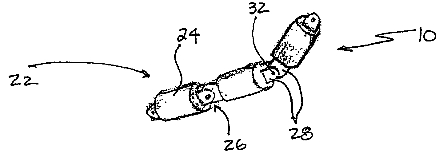
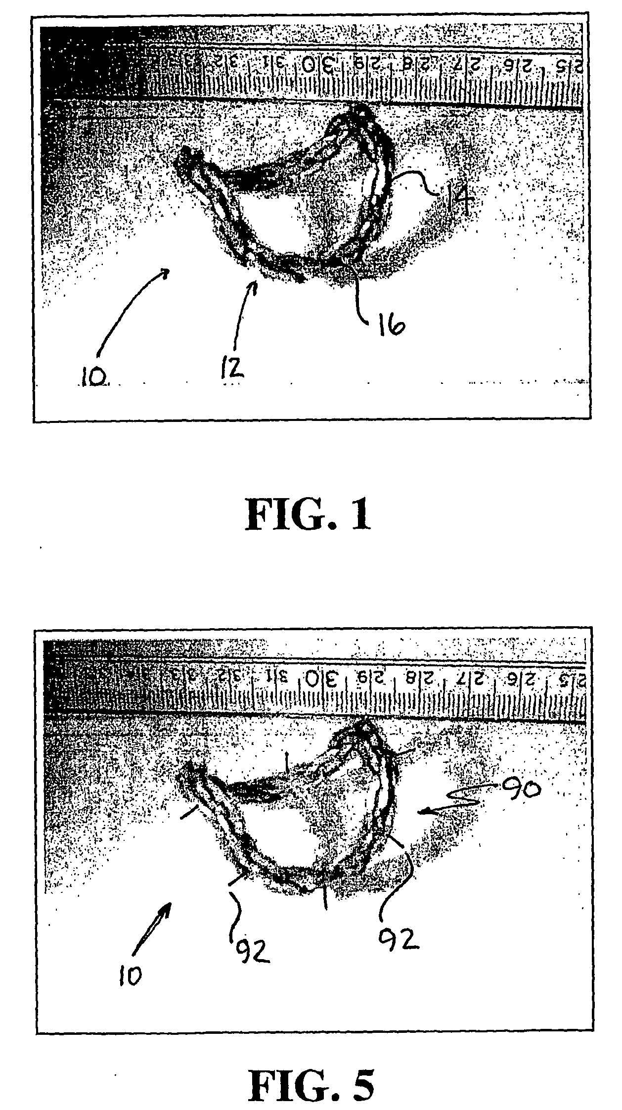
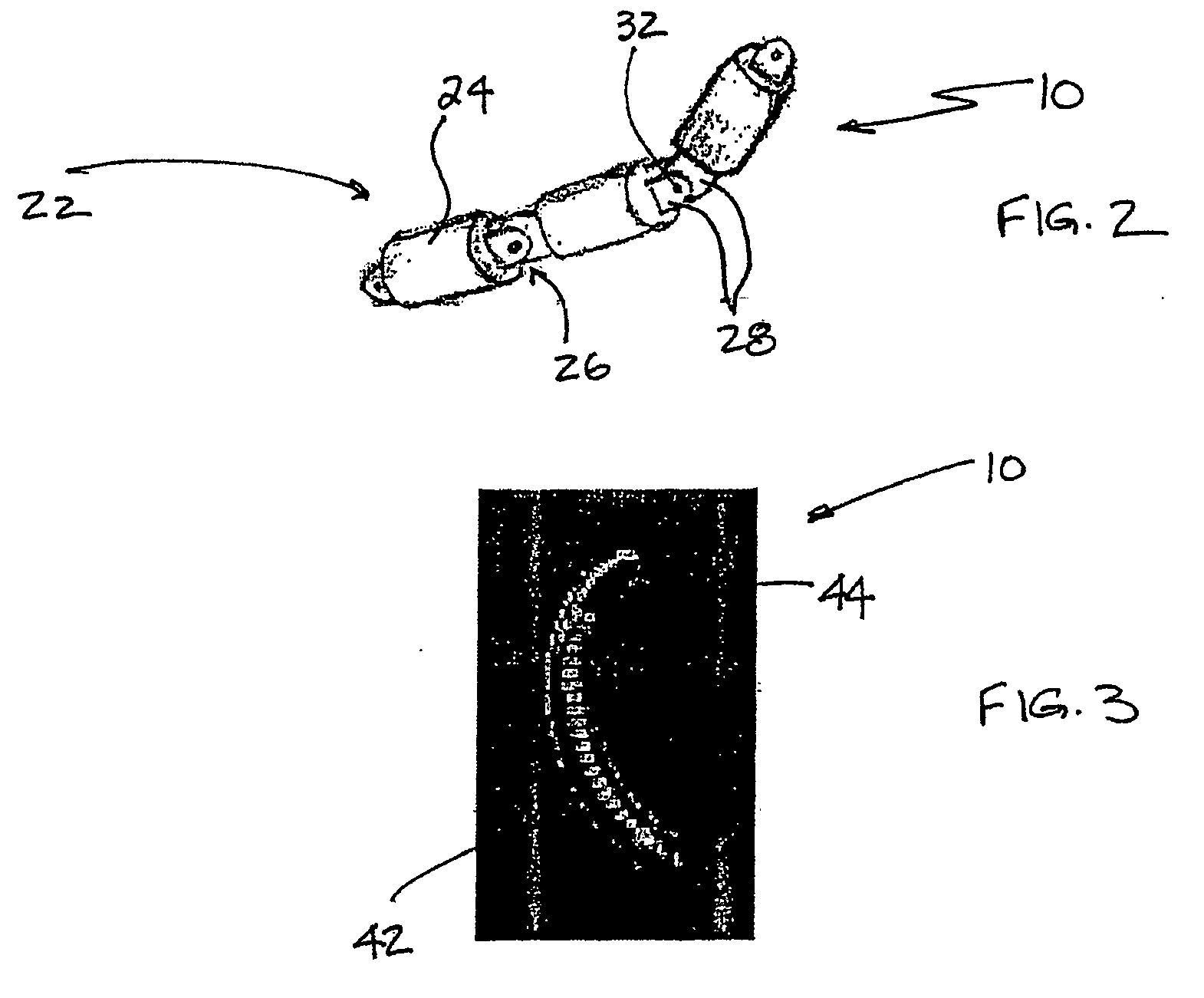
[0045] Referring now in detail to the drawing figures, wherein like reference numerals represent like parts throughout the several views, the present invention is a medical device comprises an annuloplasty chain 10 of metal, a shielding layer 60, a suturing layer 80, and an attachment system 90 to facilitate attachment of the chain 10 to annulus tissue. The chain 10 is capable of generating a three-dimensional saddle shape while maintaining its perimeter relatively constant. Thus, it maintains annular dynamics while correcting annular size after valvular dilatation.

[0046] The chain 10 maintains a relatively constant three-dimensional constant, preferably approximately 3% maximum deformation; thus, the present invention can correct annular degradation. The chain 10 is able to generate saddle-shaped annulus geometries with a saddle height to commissural ratio of up to approximately 25%.

[0047] The chain 10 is preferably fabricated from metal, but can be fabricated from other material...


PUM

PropertyMeasurementUnit
areaaaaaaaaaaa
lengthaaaaaaaaaa
heightaaaaaaaaaa

Abstract

An annuloplasty chain (10) is disclosed. The chain (10) can be fabricated from metal, and include a shielding layer (60) and a suturing layer (80).

Description

BENEFIT CLAIMS TO PRIOR APPLICATIONS [0001] This application claims the benefit of U.S. Provisional Application No. 60 / 482,393, filed 25 Jun. 2003.GOVERMENT INTERESTS [0002] This invention was made in part during work supported by the U.S. Government, including grants from the National Institutes of Health (NIH) E17-649 and HL52009. The government may have certain rights in the invention.BACKGROUND OF THE INVENTION [0003] 1. Field of the Invention [0004] This invention relates generally to the field of prostheses for cardiac valve repair, and specifically to an annuloplasty implant device incorporating a chain. [0005] 2. Description of Related Art [0006] A frequently used method for eliminating some pathological alterations of the mitral and tricuspid valves of the heart is that of reinstating the correct shape and dimensions of the valve annulus by means of surgical procedures known as annuloplasty. Annuloplasty includes surgically implanting a supporting prosthesis on the dilated ...

Claims


Application Information

Patent Timeline
Patent Type & Authority Applications(United States)
IPC IPC(8): A61F2/24A61FA61F2/06
CPCA61F2/2445A61F2/2457
Inventor JIMENEZ, JORGEYOGANATHAN, AJITHE, ZHAOMING
Owner GEORGIA TECH RES CORP
Why Eureka
Try Eureka