

Interactive control system for an HVAC system
- Summary
- Abstract
- Description
- Claims
- Application Information
AI Technical Summary
Problems solved by technology
Method used
Image

Examples
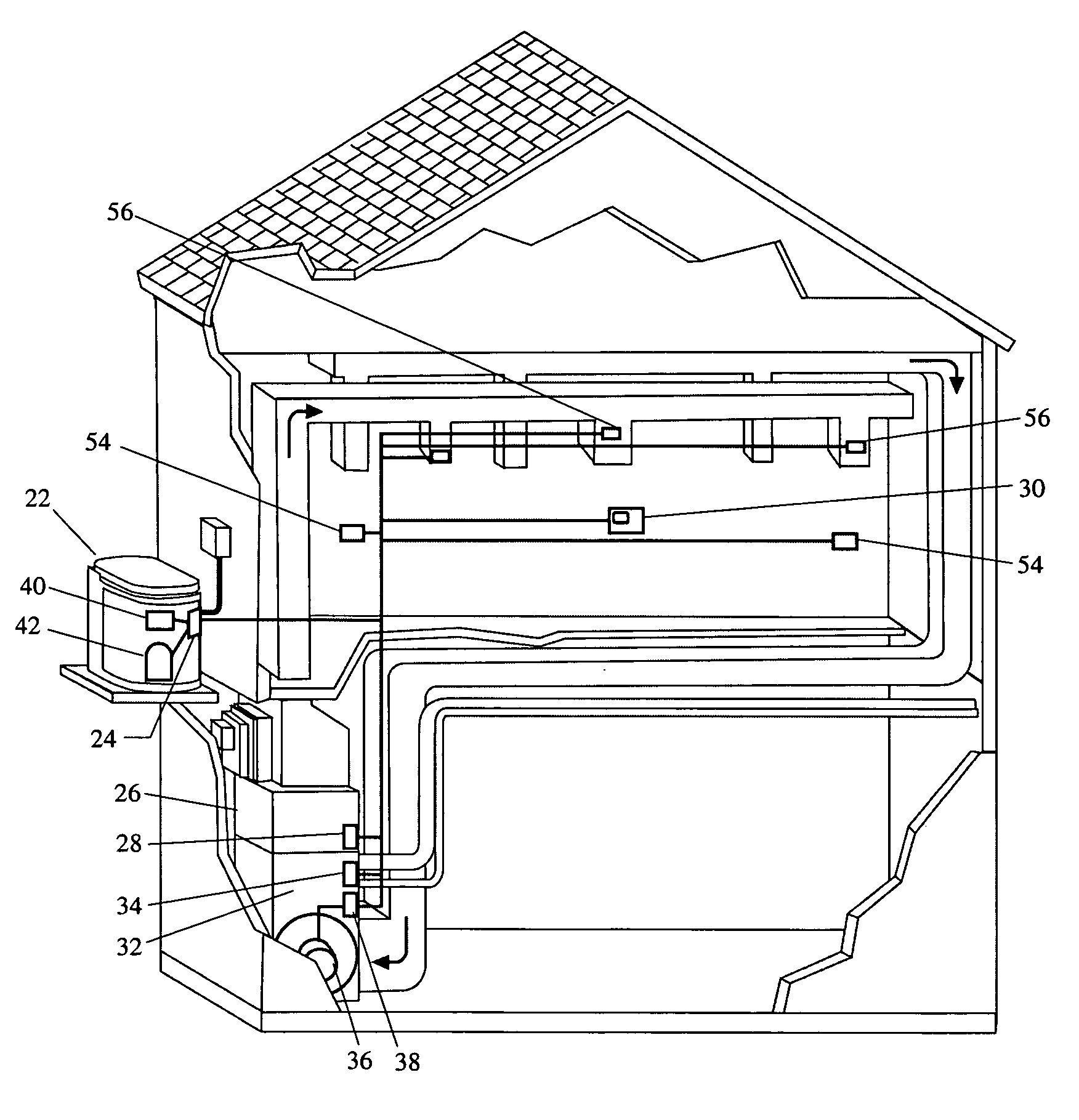
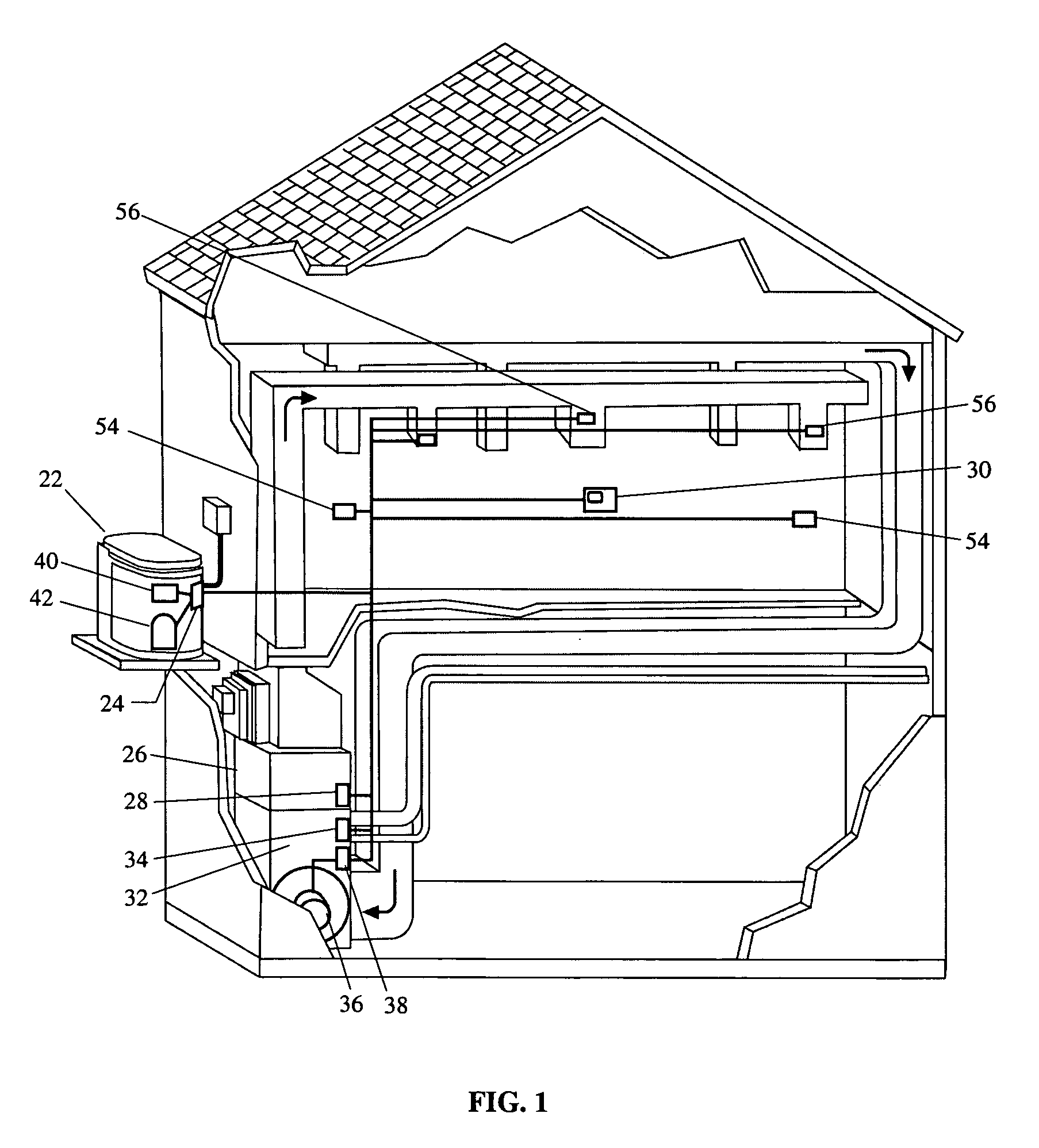
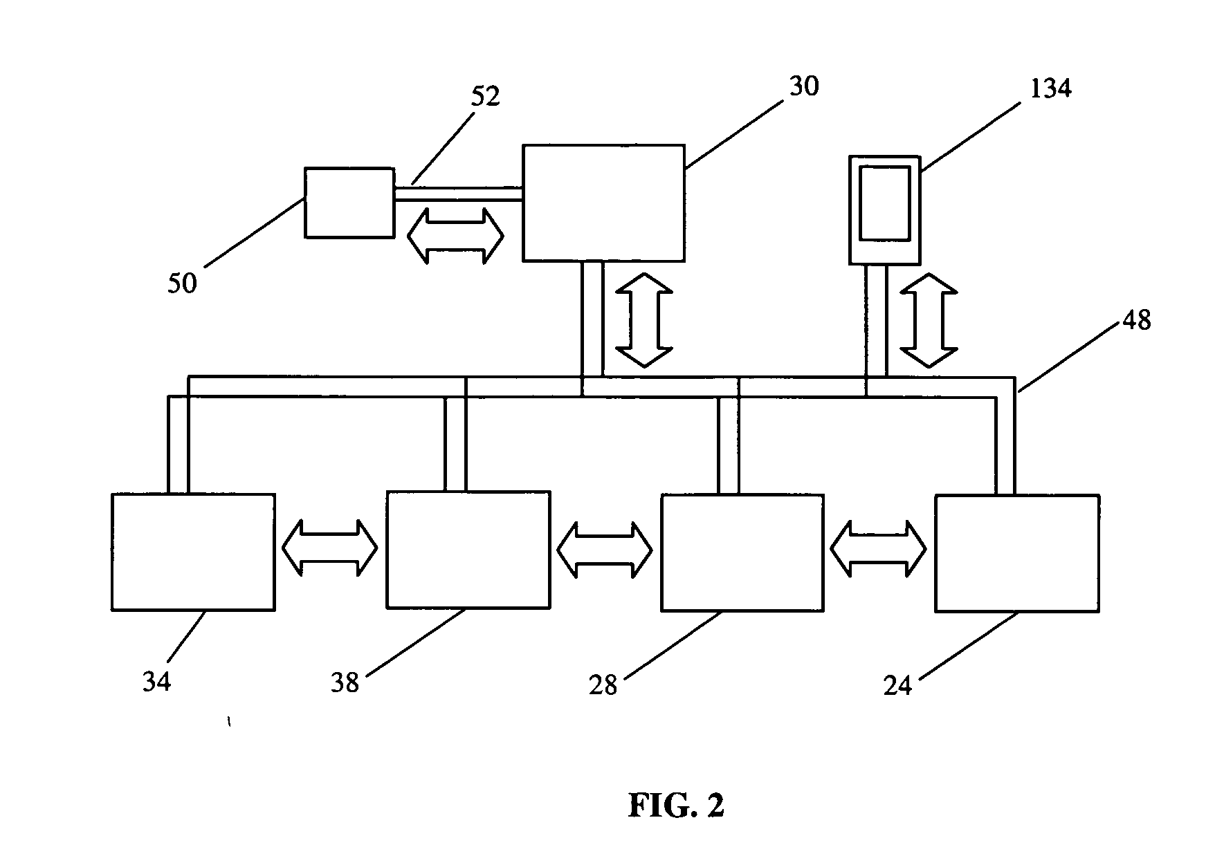
first embodiment
[0011] In this first embodiment, the various controllers that control individual components within the HVAC system are further capable of bi-directional communication with each other, to interactively control and improve the operation of the HVAC system. For example, an HVAC system may comprise an indoor blower controller 28 and an outdoor unit controller 24 that communicate via a network that may or may not be in connection with the thermostat 30. The thermostat 30 may request low stage cooling by sending a conventional 24 volt signal via a “Y1” line to the indoor blower controller 28 and to the outdoor unit controller 24. During the request for cooling from the thermostat 30, the indoor blower controller 28 may experience a blower motor failure and communicate the fault to the outdoor unit controller 24, which would responsively discontinue operation of the outdoor unit to protect the compressor 40 from being damaged. In this example, the communication between the individual contr...
second embodiment
[0034] In the present invention, the indoor blower controller 28 of the present invention comprises a processor 100 for controlling at least one switching relay 102 for controlling the selection of a plurality of operating speeds of the indoor blower motor 36. The indoor blower controller 28 may either receive a call for cool from a thermostat 30 via a conventional 24 volt “Y1” first stage cooling signal or a full capacity “Y2” second stage cooling signal, or may alternately receive a first or second stage cooling signals via the network 48 where thermostat 30 is connected to the network. The processor 100 of the indoor blower controller 28 may also receive sensed return air temperature and supply air temperature from temperature sensors 104 and 106 across the A-coil and / or heat exchanger. The processor 100 of the indoor blower controller 28 may also receive the sensed temperatures at the inlet and outlet of the a-coil. In one embodiment of the present invention, the indoor blower c...
PUM
 Abstract
Description
Claims
Application Information