
Effort-saving bicycle and transmission crank

a technology of transmission crank and bicycle, which is applied in the direction of pedal propulsion, foot-driven levers, vehicle components, etc., can solve the problems of easy loss of mechanical motive power, easy fatigue of leg muscles, and easy fatigue of riders, so as to save effort and smoothness, and accelerate the effect of driving the bicycl

Inactive Publication Date: 2006-08-24
YUAN CHIN CHIEN
View PDF18 Cites 4 Cited by
  • Summary
  • Abstract
  • Description
  • Claims
  • Application Information

AI Technical Summary

Benefits of technology

[0006] It is one objective of the present invention to provide a transmission mechanism for a bicycle, which can rapidly drive the bicycle and achieve the performances of saving effort and smoothness.
[0007] It is another objective of the present invention to provide a bicycle with a transmission crank having an effective force-applied arm, which can rapidly drive the bicycle and achieve the performances of saving effort and smoothness.
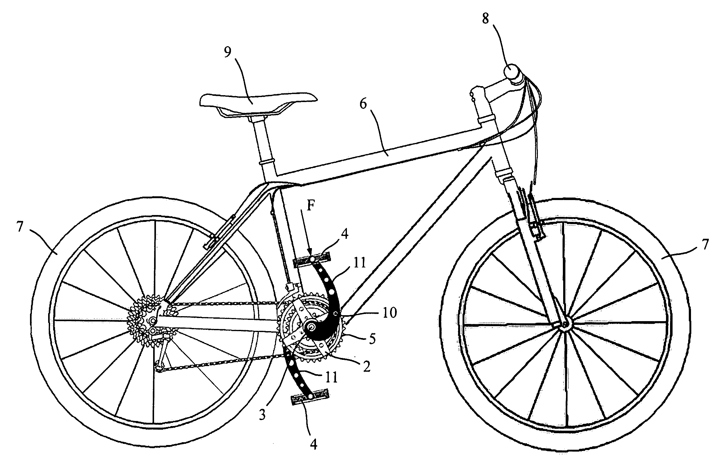
[0008] In order to achieve the above-mentioned objectives, a bicycle according to the present invention comprises a frame; two wheels pivotably disposed respectively on a front side and rear side of a lower portion of the frame; a gear-driving disc pivotably disposed proximate to a central portion of a lower portion of the frame; a handlebar installed on a front side of an upper portion of the frame; a seat pad installed proximate to a central portion of an upper portion of the frame; two cranks each of which having one respective end pivotably disposed at a transmission axle of two sides of the gear-driving disc; two pedals pivotably disposed on the other respective ends of the two cranks. When circumferential stepping movements are performed on the pedals of the bicycle, a force-applied point of the crank may in advance effectively pass through an upper death point upon performing a circumferential stepping movement and defer passing through a lower death point, and a death angle of a maximum force-applied point upon performing a circumferential stepping movement is eliminated.

Problems solved by technology

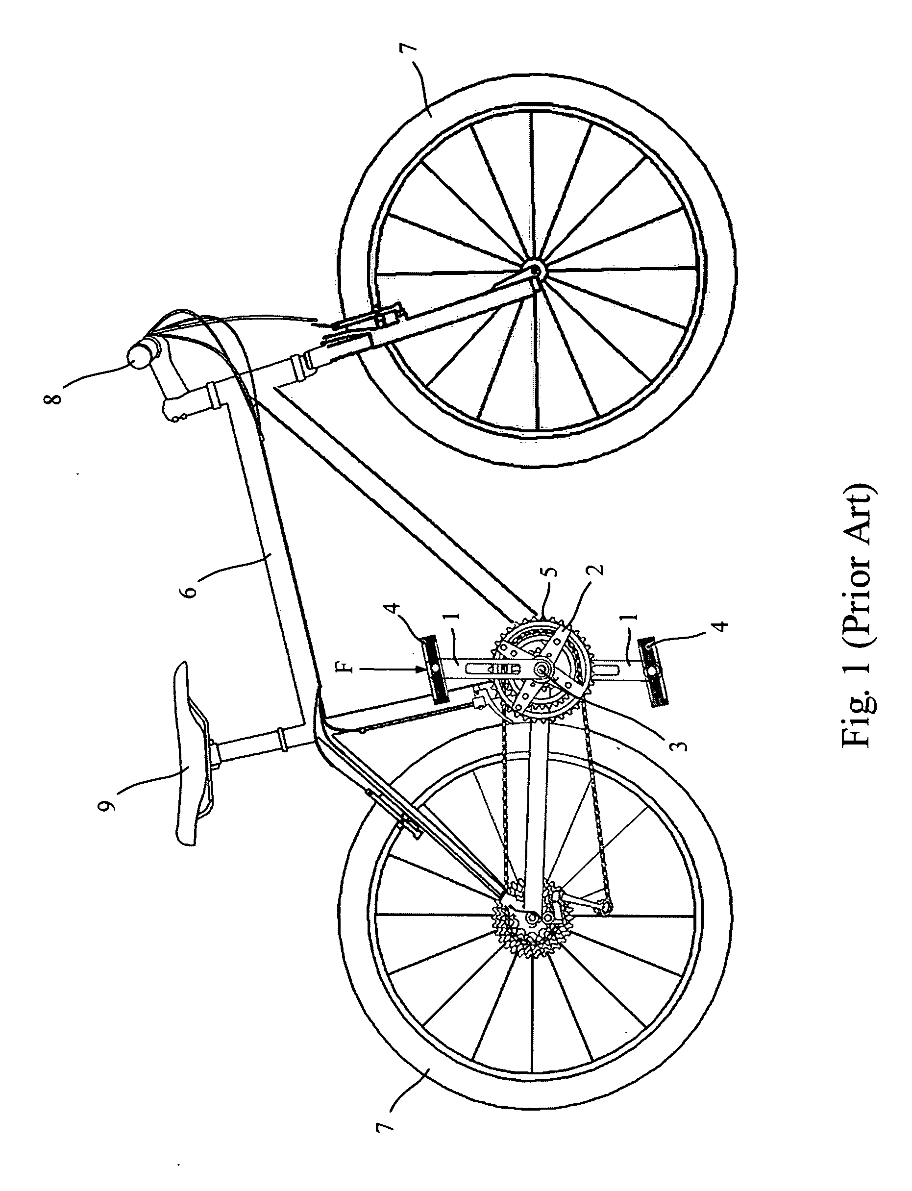
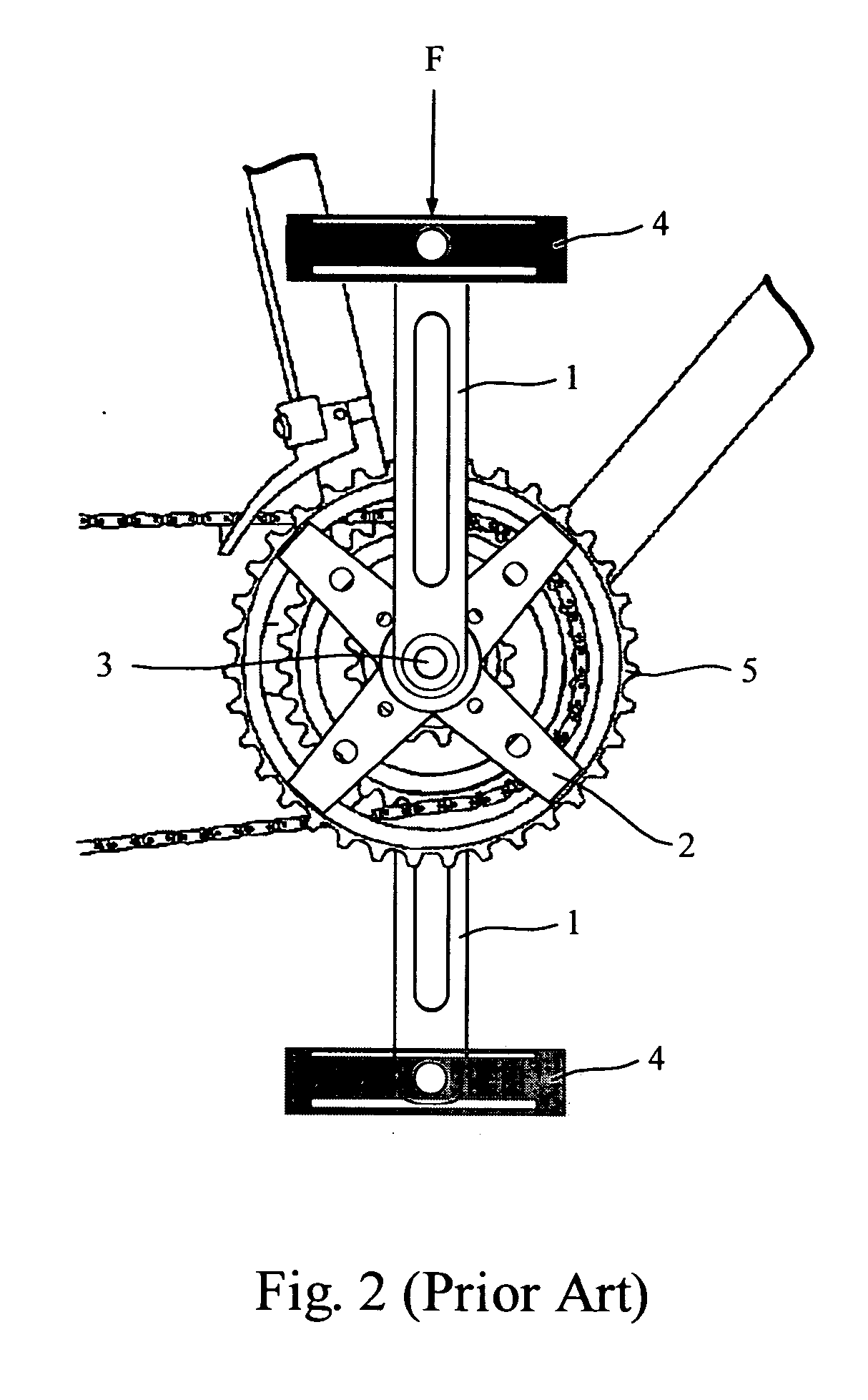
Moreover, the legs of the rider need to repeatedly perform the circumferential stepping movement to drive the bicycle, however, when the leg repeatedly reaches the upper death point at which an instantaneous maximum force exerts, the leg muscle is easy to be weary.
Such a conventional design of the bicycle transmission system is easy to lose the mechanical motive power.
The rider easily gets tired and the efficiency for driving the bicycle is relatively worse.

Method used


Image

  • Effort-saving bicycle and transmission crank
  • Effort-saving bicycle and transmission crank
  • Effort-saving bicycle and transmission crank

Examples


Embodiment Construction

[0018] Although the present invention has been described in considerable detail with reference to certain preferred embodiments thereof, however prior to this description, it should be understood that those skilled in the art can easily make changes to the present invention described herein and the same performance as the present invention is obtained. Therefore, it is to be understood that the following description is a general disclosure to those skilled in the art and is not restrictive of the present invention.

[0019] Referring to FIG. 3 and FIG. 4, a side view of the bicycle according to the present invention and a partial enlarged view of curved cranks and pedals of the present bicycle are respectively shown. The bicycle of the present invention comprises a frame 6; two wheels 7 pivotably disposed respectively on a front side and rear side of a lower portion of the frame 6; a gear-driving disc 2 pivotably disposed proximate to a central portion of the lower portion of the fram...


PUM


Abstract

This invention provides an effort-saving bicycle and transmission cranks comprising: a frame; two wheels pivotably disposed respectively on a front side and rear side of a lower portion of the frame; a gear-driving disc pivotably disposed proximate to a central portion of a lower portion of the frame; a handlebar installed on a front side of an upper portion of the frame; a seat pad installed proximate to a central portion of an upper portion of the frame; two cranks each of which having one end pivotably disposed at a transmission axle of two sides of the gear-driving disc; two pedals pivotably disposed respectively on the other ends of the two cranks. A force-applied point of the crank may in advance effectively pass through an upper death point and defer passing through a lower death point upon performing a circumferential stepping movement at the pedals, and eliminating a death angle coming from a maximum force-applied point upon performing a circumferential stepping movement at the pedals.

Description

BACKGROUND OF THE INVENTION [0001] 1. Field of the Invention [0002] The present invention relates to an effort-saving bicycle and transmission cranks, and especially to a bicycle having effort-saving transmission cranks. [0003] 2. Description of the Related Art [0004] Due to light-weighted, convenience and economical characteristic, bicycles have been widely used as transportation vehicles over one hundred years and become convenient transportation vehicles now. Force needs to be applied on the pedals of the bicycle so as to drive the wheels of the bicycle to rotate by a link chain and making the bicycle advance. Among other things, the bicycles are not replaceable in high-level leisure entertainment and exercise for health at the present day. As persisting evolution of science and technology, the life will be changed and the environment also will be changed. However, an environment-protective bicycle will be able to continue making happiness and bringing convenience in the daily li...

Claims


Application Information

Patent Timeline
IPC IPC(8): B62M1/02B62M1/36B62M3/00B62M5/00
CPCY10T74/2164B62M3/00
Inventor YUAN, CHIN-CHIEN
Owner YUAN CHIN CHIEN
Learn More