Mobile milling head with torque motor drive

a motor drive and milling head technology, applied in the field of work spindle heads, can solve the problems of high wear and the damage of the milling head or the milling tool, and the inability to compensate for the damage of the worm gear, etc., and achieve the effect of accurate positioning of the milling head and the milling spindle, high surface quality, and large and heavy workpieces

Inactive Publication Date: 2008-12-30
F ZIMMERMAN GMBH & CO KG
View PDF13 Cites 27 Cited by
  • Summary
  • Abstract
  • Description
  • Claims
  • Application Information

AI Technical Summary

Benefits of technology

[0005]Independently of the type of gear used, the stiffness of the machine tool is usually reduced, especially since several reduction stages are frequently needed to achieve the required high torque at the gear output. The reduced stiffness impairs machining accuracy. Furthermore, the assembly and maintenance cost of these types of drive gears are relatively high. In addition, the slew rate is limited. Since modern linear axes can be driven faster and faster with linear motors and rapid corrective movements of the filling head and milling spindle are required when milling complex surfaces in order to always achieve the angular position of the tool needed for the contour of the surface being machined, high rotational and slew rates are required.
[0024]The portal milling machine according to the invention also permits extremely large and heavy workpieces to be completely milled in one piece without requiring regrinding or other refinishing. The portal milling machine can demonstrate a stationary clamping table for the workpiece, said clamping table preferably being solidly anchored to the foundation, and stable sidestands which support the portal. The masses to be moved are then always the same and relatively small. The portal milling machine according to the invention is able, for the sake of an example, to machine steel workpieces with a mass of 15 metric tons in a machine space dimensioned 4×3×1.5 m. The feed devices for the linear axes and the first and second drive device, in combination with appropriate measuring systems and a CNC controller, provide for accurate positioning of the milling head and milling spindle during the machining operation.

Problems solved by technology

Some disadvantages are associated with the drive gears, however.
For example, a worm gear is subjected to high wear for which there is no compensation.
Because of the self-locking effect of the worm gear, there also exists the danger that the milling head or milling tool will be damaged when it bumps against an obstacle.
The reduced stiffness impairs machining accuracy.
Furthermore, the assembly and maintenance cost of these types of drive gears are relatively high.
In addition, the slew rate is limited.

Method used


Image

  • Mobile milling head with torque motor drive
  • Mobile milling head with torque motor drive
  • Mobile milling head with torque motor drive

Examples


Embodiment Construction

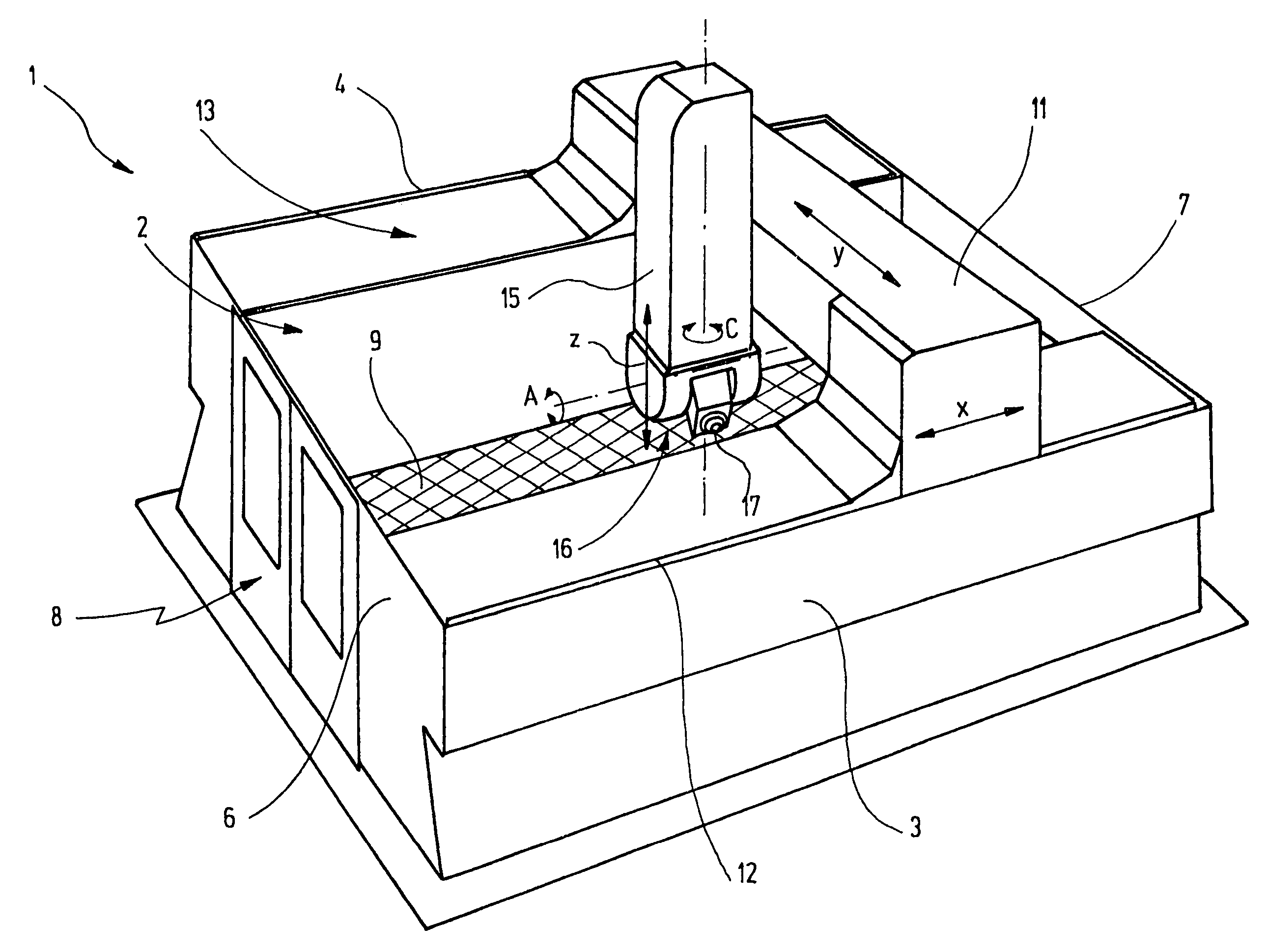
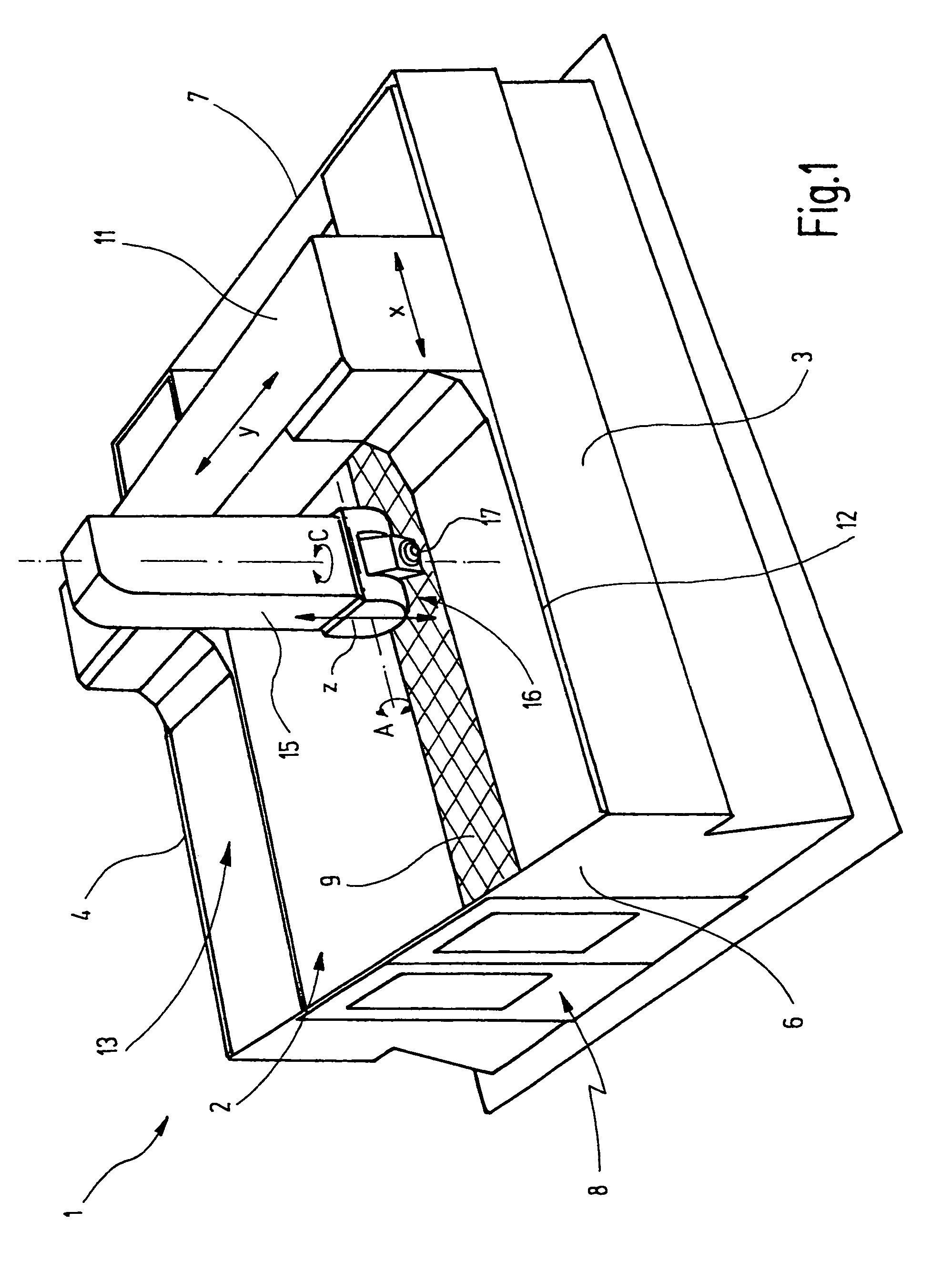
[0031]FIG. 1 schematically illustrates a milling machine 1 according to the present invention configured in a portal design. The portal milling machine 1 demonstrates a machine space 2 which is defined by massively configured lateral partition walls 3, 4, a front wall 6 and a rear wall 7 and is accessible through an access door 8 attached to the front wall 6. A machine table 9 for receiving a workpiece is provided in the machine space 2 and is preferably solidly anchored to the foundation. As evident in FIG. 1, the machine space 2 and table 9 are arranged to receive relatively large workpieces, like those used for example in mold or model making in the automotive or aviation industries.

[0032]The milling machine is configured in portal design and demonstrates a portal 11, which is supported on the sidestands 3, 4 and can be driven in a horizontal X direction shown by a double arrow and is precisely guided by a guides, which are provided on both sidestands and only implied here. An ex...


PUM

PropertyMeasurementUnit
torqueaaaaaaaaaa
reductionaaaaaaaaaa
surface qualityaaaaaaaaaa

Abstract

A milling head (16) for a milling machine (1) arranged for machining large-size workpieces comprises a fork 18, which is rotatably arranged around a first axis (C) and demonstrates a pair of fork arms (21, 22), which are separated from one another, a spindle device (23), which is arranged between the fork arms and rotatable around a second axis A, a first torque motor (42), which is coupled to the fork 18 for directly driving and controlling of the rotation of the fork around the first axis (C), and a second torque motor (57) for driving and controlling the rotation of the spindle around the second axis (A), said second torque motor being coupled to the spindle device (23) by means of a one-stage toothed gearing (61), which is mechanically clamped free of backlash. The configuration according to the invention is arranged to achieve high torque with high dynamic stiffness and small interference contour of the milling head (16).

Description

BACKGROUND OF THE INVENTION[0001]The present invention relates to a work spindle head for a machine tool spindle, especially a milling head for a milling spindle, comprising torque motors to rotate the spindle around at least two different axes. In addition, the present invention relates to a milling machine which is equipped with this type of milling head and constructed with portal design. Such portal milling machines are frequently used for toolmaking, mold making and model making or production in the automotive, aviation and space industries and in other applications in which complex surfaces must be configured on large tools with extremely high surface quality and processing speed.SUMMARY OF THE INVENTION[0002]One portal milling machine known in practice demonstrates a portal which is supported on sidestands and can be driven in the X direction by a clamping table solidly fastened to the foundation. An extension arm, which bears a milling head that can be adjusted in the Z dire...

Claims


Application Information

Patent Timeline
Patent Type & Authority Patents(United States)
IPC IPC(8): B23C1/12
CPCB23C1/002B23C1/12B23Q1/5406B23C2215/04Y10T409/307672B23Q2210/004B23Q2220/006Y10T409/308288
Inventor BRUNEMANN, BERNHARD
Owner F ZIMMERMAN GMBH & CO KG
Why Eureka
Try Eureka