Microactuator

a micro-actuator and actuator technology, applied in the field of micro-actuators, can solve the problems of low rigidity increased mass of the movable section, and increased requiring a greater driving force, and achieve the effect of high rigidity and low mass

Inactive Publication Date: 2005-10-27
PANASONIC CORP
View PDF13 Cites 27 Cited by
  • Summary
  • Abstract
  • Description
  • Claims
  • Application Information

AI Technical Summary

Benefits of technology

[0012] In order to overcome the problems described above, preferred embodiments of the present invention provide a microactuator comprising a movable section which is capable of multi-axial tilting and which has a low mass and a high rigidity, such that the microactuator is capable of high-speed operation at a low voltage.

Problems solved by technology

However, the above optical deflector has the following problems.
As a result, the movable section has a low rigidity.
However, if the height of the comb teeth is made so high as to attain a necessary level of rigidity for the movable section, the mass of the movable section will also increase, thus requiring a greater driving force for driving the movable section.
Moreover, the increased mass of the movable section also leads to a lower resonance frequency of the movable section, so that it becomes difficult to drive the movable section at a fast speed.
If the comb tooth height is increased, the mass of the movable section will be increased, thus leading to the aforementioned problems of a large driving force being required and the inability to drive the movable section at a fast speed.

Method used


Image

  • Microactuator
  • Microactuator
  • Microactuator

Examples


embodiment 1

(Embodiment 1)

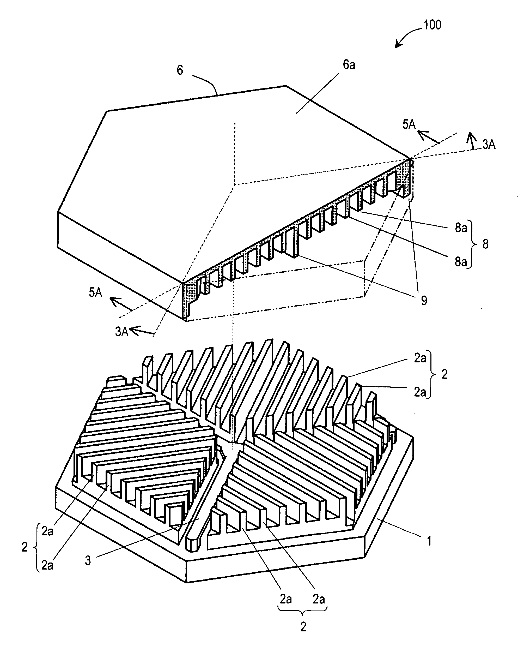
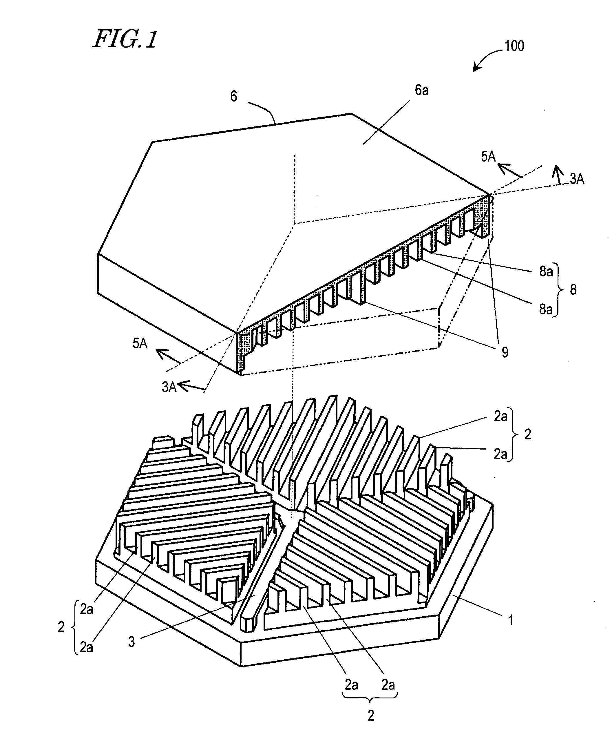
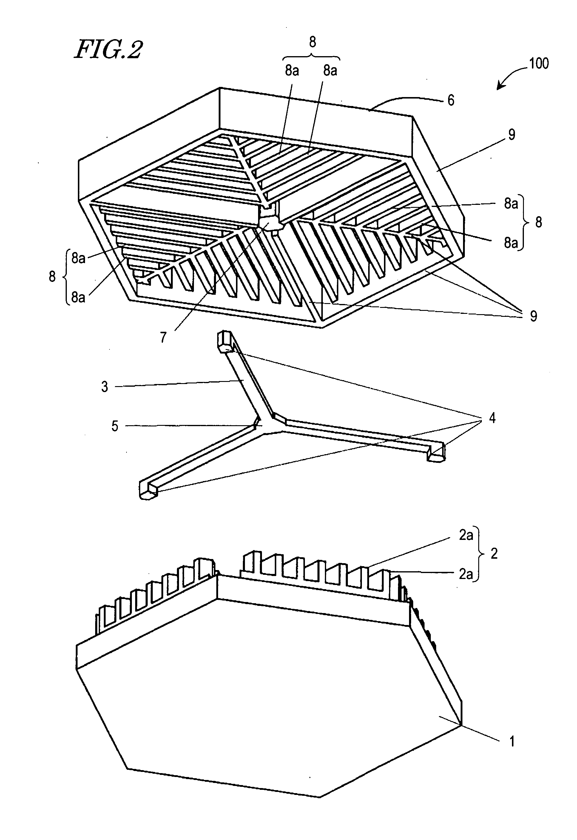
[0046] With reference to FIGS. 1 to 6, a microactuator according to a first embodiment of the present invention will be described.

[0047] Firstly, FIGS. 1 and 2 will be referred to, which are exploded perspective views schematically showing the microactuator 100 of the present embodiment. Specifically, FIG. 1 shows the microactuator 100 as viewed obliquely from above, whereas FIG. 2 shows the microactuator 100 as viewed obliquely from below. In FIG. 1, a portion of the movable section is cut away in order to show a rear cross-sectional view of the movable section. The microactuator 100 is produced by a micromachining technique employing a semiconductor process or a MEMS (Micro Electro Mechanical System) technique.

[0048] The microactuator 100 includes: a base 1; a plurality of first comb electrodes 2 supported by the base 1; a movable section 6; and an elastic supporting member 3 for supporting the movable section 6 in such a manner as to allow the movable section 6 to...

embodiment 2

(Embodiment 2)

[0067] Referring to FIG. 7, a microactuator according to a second embodiment of the present invention will be described.

[0068]FIG. 7 is a plan view schematically showing a movable section 16 according to the present embodiment. In the present embodiment, the microactuator 100 comprises the movable section 16, instead of the movable section 6.

[0069] In addition to the component elements employed in the movable section 6 of Embodiment 1, the movable section 16 additionally comprises at least one reinforcement rib 11 (a plurality of such reinforcement ribs 11 are illustrated in the present embodiment). Each reinforcement rib 11 extends through a corresponding one of the second comb electrodes 8, and extends along a direction perpendicular to the direction in which the second comb teeth 8a of that second comb electrode 8 extend. Each reinforcement rib 11 has the same height as that of those reinforcement rib 9 whose height is greater than that of the second comb teeth 8a...

embodiment 3

(Embodiment 3)

[0070] Referring to FIG. 8, a microactuator according to a third embodiment of the present invention will be described.

[0071]FIG. 8 is a plan view schematically showing a movable section 26 according to the present embodiment. In the present embodiment, the microactuator 100 comprises the movable section 26, instead of the movable section 6.

[0072] Instead of the second comb electrodes 8 in the movable section 6 of Embodiment 1, the movable section 26 includes a plurality of second comb electrodes 28. Each second comb electrode 28 includes a plurality of second comb teeth 8b in the form of concentric circles. In the present embodiment, the first comb teeth 2a are also shaped as concentric circles (not shown), correspondingly to the second comb teeth 8b. The second comb teeth 8b, each of which lies perpendicular to the radially-extending reinforcement ribs 9, enhances the rigidity of the movable section 26. Since the positional relationship between the first comb elect...


PUM


Abstract

There has been a trade-off between the rigidity and the mass of a movable section of a microactuator, and also between the rigidity of the movable section and the electrostatic force. A microactuator 100 includes: a base 1; a first comb electrode 2 supported by the base 1; a movable section 6 having a second comb electrode 8 opposing the first comb electrode 2, and at least one reinforcement rib 9 protruding toward the base 1; and an elastic supporting member 3 for supporting the movable section 6 so as to allow the movable section 6 to be displaced with respect to the base 1. The height of the second comb electrode 8 is different from the height of the at least one reinforcement rib 9.

Description

BACKGROUND OF THE INVENTION [0001] 1. Field of the Invention [0002] The present invention relates to a microactuator comprising comb electrodes for causing displacement of a movable section by means of electrostatic force. The microactuator of the present invention may be used as, for example, a micromirror device whose movable section includes a light reflecting surface. [0003] 2. Description of the Related Art [0004] A microactuator, as one application of micromachining techniques, may be used as an optical scanning device as in a laser printer, a scanner, or a display, or as an optical switching device for switching light which goes into or out of an optical fiber, for example. [0005] Japanese Laid-Open Patent Publication No. 2000-147419 discloses a microactuator comprising comb electrodes, which functions as an optical deflector. A movable section of this optical deflector includes a mirror surface functioning as a light reflecting surface. The movable section is supported by tw...

Claims


Application Information

Patent Timeline
Patent Type & Authority Applications(United States)
IPC IPC(8): B81B3/00G02B26/08H02N1/00
CPCB81B3/00B81B3/0062H02N1/008B81B2201/042G02B26/0841B81B2201/033B81B2203/053B81B2203/058
Inventor KUROZUKA, AKIRAMUSHIKA, YOSHIHIROKAJINO, OSAMU
Owner PANASONIC CORP
Why Eureka
Try Eureka