Programmable clock booster system

Active Publication Date: 2006-08-24
ANALOG DEVICES INC
View PDF19 Cites 18 Cited by
  • Summary
  • Abstract
  • Description
  • Claims
  • Application Information

AI Technical Summary

Benefits of technology

[0013] It is a further object of this invention to provide su

Problems solved by technology

Because prior art clock boosters or voltage doublers are designed to boost the output voltage to double the supply voltage, they do not provide a boosted voltage that is between the supply voltage and double the supply voltage that may be useful in many designs.
However, such a design requires a second low impedance voltage source to provide the boosting voltage and this requires extra power.
However, the circuit relies on selecting the attenuating capacitor for a spec

Method used


Image

  • Programmable clock booster system
  • Programmable clock booster system
  • Programmable clock booster system

Examples


Embodiment Construction

[0034] Aside from the preferred embodiment or embodiments disclosed below, this invention is capable of other embodiments and of being practiced or being carried out in various ways. Thus, it is to be understood that the invention is not limited in its application to the details of construction and the arrangements of components set forth in the following description or illustrated in the drawings. If only one embodiment is described herein, the claims hereof are not to be limited to that embodiment. Moreover, the claims hereof are not to be read restrictively unless there is clear and convincing evidence manifesting a certain exclusion, restriction, or disclaimer.

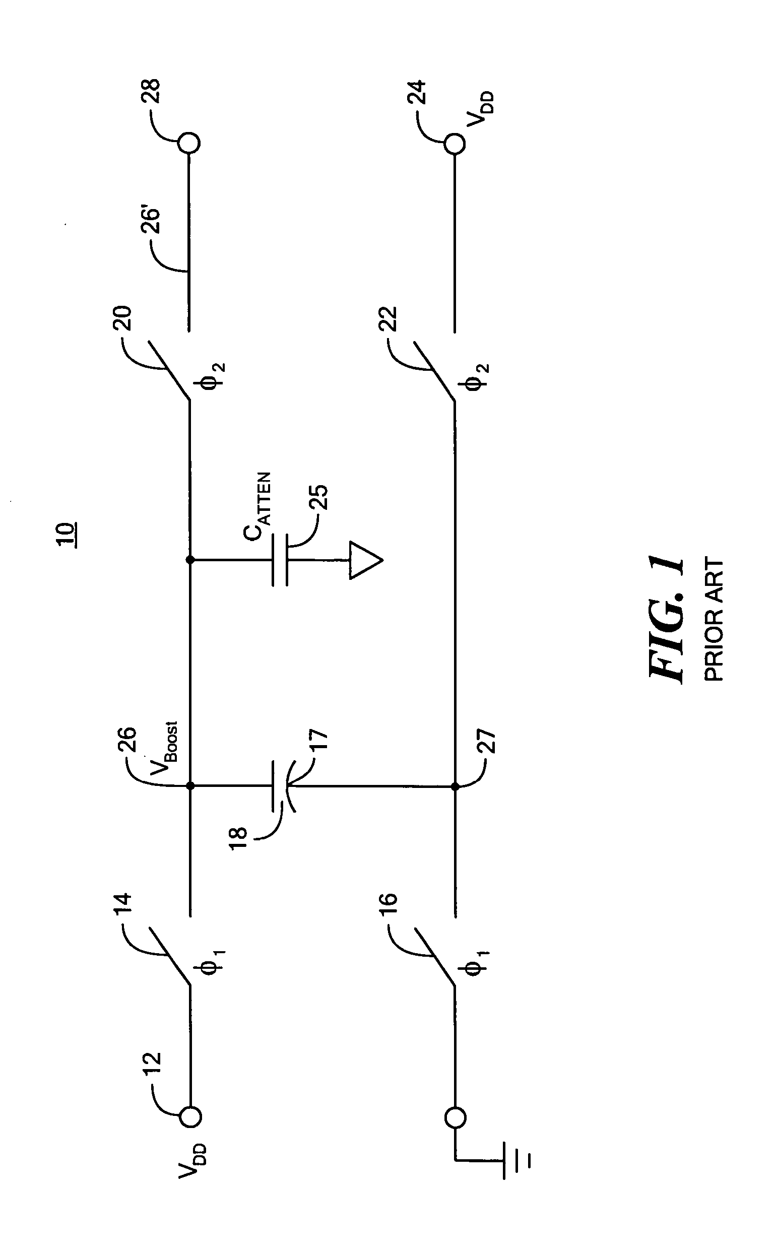
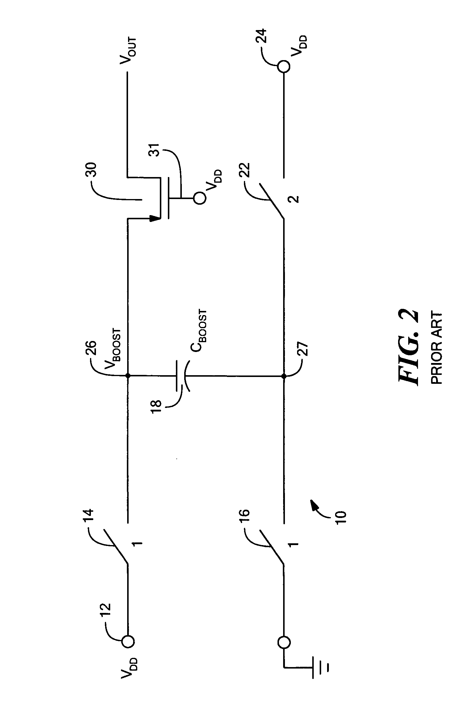
[0035] As discussed in the Background section above, conventional clock booster or voltage doubler circuit 10, FIG. 1, is designed to double the input voltage VDD 12 by sampling input voltage VDD 12 in a first phase with boost capacitor 18 by closing switching devices 14 and 16 and opening switching devices 20 and 22. At ...


PUM


Abstract

A programmable clock booster system including a clock booster circuit including at least one boost capacitor connected between a first node and a second node for sampling an input voltage in a first phase and applying a boosting voltage to said second node during a second phase, and a programmable capacitor circuit connected to said first node for providing a programmable boosted voltage on said first node during said second phase.

Description

RELATED APPLICATIONS [0001] This application claims priority of U.S. Provisional Application No. 60 / 636,725 filed Dec. 16, 2004, incorporated by reference herein.FIELD OF THE INVENTION [0002] This invention relates to an improved programmable clock booster system. BACKGROUND OF THE INVENTION [0003] Many electrical circuits require voltages to be boosted higher than the supply voltage of the circuit. One prior art method to provide a boosted voltage is a switched capacitor voltage doubler circuit. This method samples an input voltage, e.g., the supply voltage, on a capacitor during one phase and then connects the capacitor in series with the input voltage during a second phase to create a boosted output voltage at the top plate of the capacitor is equal to twice the input voltage. This same circuit is often used as a clock booster by connecting the capacitor in series with a clock voltage during the second phase. Because prior art clock boosters or voltage doublers are designed to bo...

Claims


Application Information

Patent Timeline
IPC IPC(8): G05F1/10
CPCH02M3/073
Inventor KELLY, DANIEL F.SINGER, LAWRENCE A.
Owner ANALOG DEVICES INC
Why Eureka
Try Eureka