Magnetic element and method of manufacturing magnetic element

a technology of magnetic elements and magnetic elements, applied in the field of magnetic elements, can solve the problems of difficult reduction of resistance to electric current, certain limitation in the downsizing of magnetic elements of drum types, and leakage of magnetic flux to the outside, so as to improve the direct current superposition characteristic, improve the magnetic permeability of magnetic members, and facilitate manufacturing

Active Publication Date: 2006-08-24
SUMIDA CORP
View PDF15 Cites 49 Cited by
  • Summary
  • Abstract
  • Description
  • Claims
  • Application Information

AI Technical Summary

Benefits of technology

[0013] The present invention has been made in view of the above-described situation, and an object thereof is to provide a magnetic element capable of enhancing the magnetic permeability of a magnetic member and improving a direct current superposition characteristic thereof, the magnetic element which can be easily manufactured, and a method of manufacturing the magnetic element.

Problems solved by technology

However, when the air gap 103 exists, there is a problem of magnetic flux leakage to the outside.
In other words, there is a certain degree of limitation in downsizing of the magnetic element of drum type.
Further, in addition to the problem of breakage, when downsizing of the magnetic element of drum type advances, it becomes difficult to reduce resistance to an electric current as compared to a magnetic element of large size, so that a large current cannot flow.
However, such a change leads to enlargement of the magnetic element, so that it goes against the request for downsizing.
Consequently, it is difficult to realize a magnetic element that has a large inductance, an excellent direct current superposition characteristic, and a small loss in a high frequency region.
However, the magnetic element of lamination type cannot respond to a large current due to structural limitation, magnetic characteristic limitation, and so on, and in such cases, it cannot function adequately as an inductor.
Specifically, when downsizing is advanced in either of the drum type and the lamination type, generally a characteristic thereof deteriorates.
However, when the amount of metal powder is increased in the paste, the fluidity of uncured paste is inhibited by that amount.
Accordingly, formability thereof deteriorates, and the paste cannot enter a small gap such as a space between windings of a coil, thereby causing a problem that the occurrence of defects increases.
Further, since the fluidity of the paste is low, there is also a problem that the production efficiency thereof deteriorates.
Accordingly, a manufacturing cost thereof is high due to a need of dedicated jig, or the like.

Method used


Image

  • Magnetic element and method of manufacturing magnetic element
  • Magnetic element and method of manufacturing magnetic element
  • Magnetic element and method of manufacturing magnetic element

Examples


first embodiment

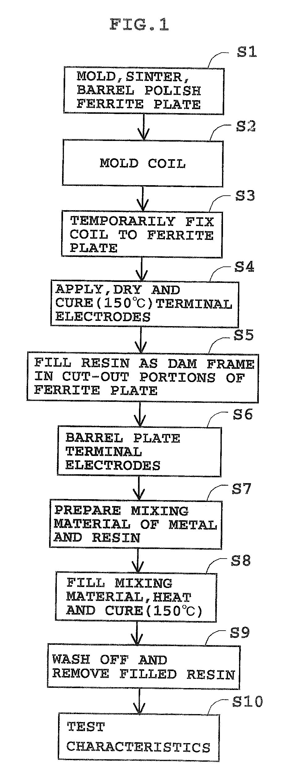
[0069] An inductance element as a magnetic element in this embodiment has realized by a simple structure an object to be usable for a power supply despite its thinness. Hereinafter, a first embodiment of the present invention will be described using examples based on FIG. 1 to FIG. 11. In each drawing, the same components are designated the same reference numerals, and overlapping descriptions thereof are omitted. In the following description, it should be noted that the structure of an inductance element will be described while showing manufacturing steps.

example 1

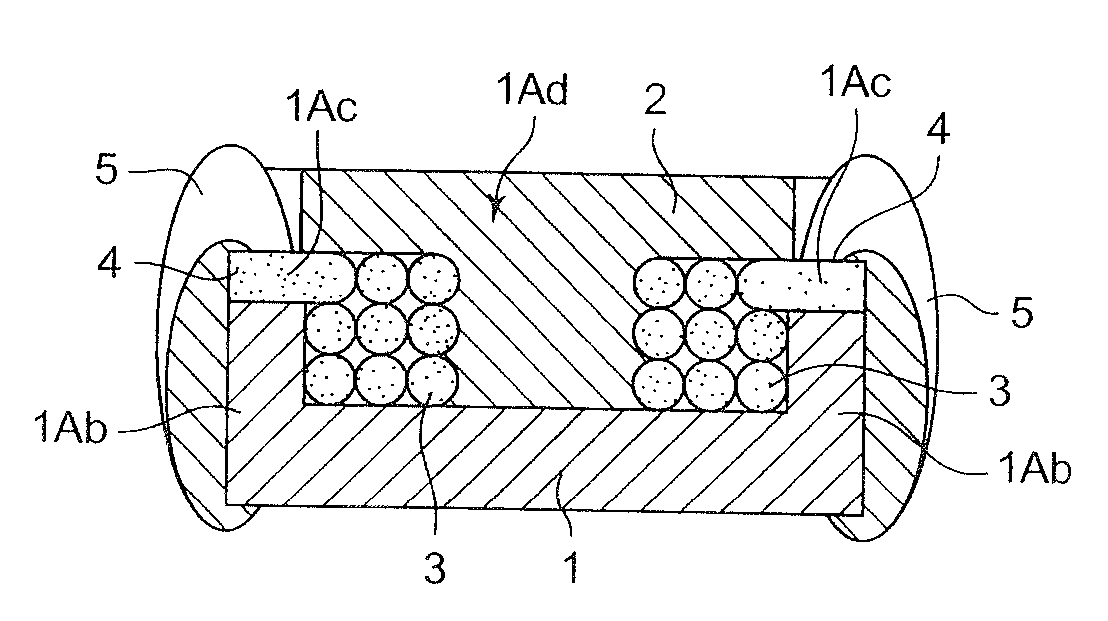
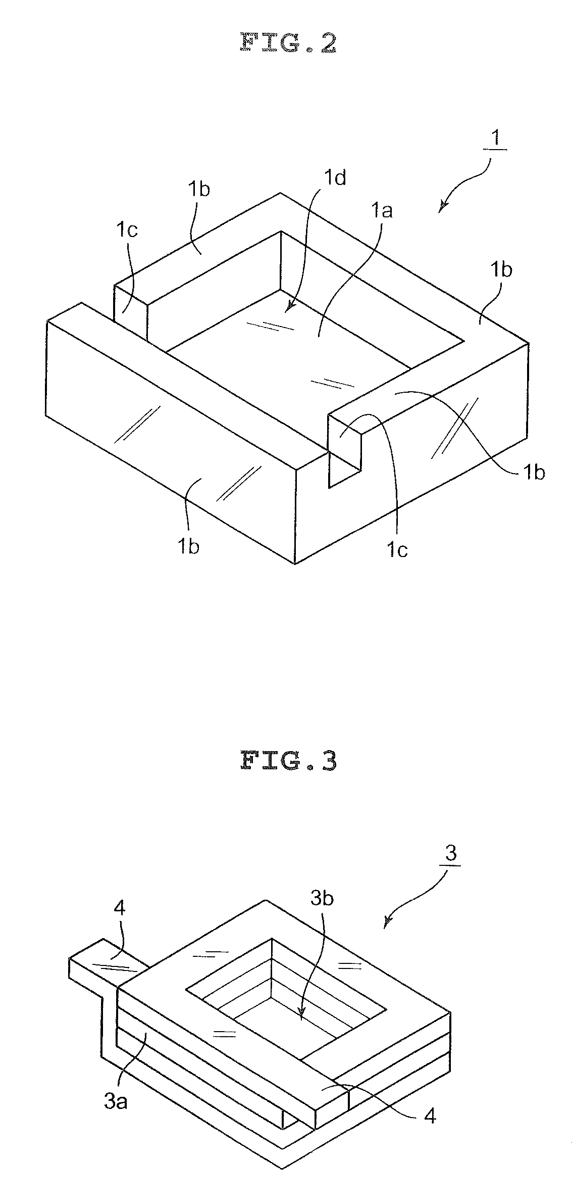
[0070]FIG. 1 shows a table of manufacturing steps of an inductance element according to an example 1. In the manufacturing steps, first, a plate 1 (ferrite plate) is molded with ferrite and sintered, and a barrel polishing is performed thereto (S1). A perspective view of the plate 1 produced as such is shown in FIG. 2. The plate 1 has a square prism shape with a bottom. Specifically, the plate 1 has a bottom 1a whose planar shape is a quadrangle and four side walls 1b surrounding an outer peripheral edge portion of the bottom 1a toward an upper side that is described later in a circumferential direction without any gaps. Thus, the plate 1 has a cup shape whose cross section is substantially a U shape. Incidentally, a portion of the plate 1 surrounded by the bottom 1a and the side walls 1b is referred to as a recessed portion 1d.

[0071] Among the side walls 1b, cut-out portions 1e, 1c are formed respectively in two opposing side walls 1b, 1b. The cut-out portions 1c, 1c are each form...

example 2

[0082] In an example 2, a coil 3A shown in FIG. 8 is used. The coil 3A is constructed by winding a conductor 3Aa which is insulation coated and has a circular cross-section or front shape. Similarly to the coil 3, the coil 3A is wound in a rectangular parallelepiped shape whose planar shape is a quadrangle in a state of having, for example 1, a square hole 3Ab at the center. Incidentally, as the coil 3A, the conductor 3Aa wound in a cylindrical shape may be used. Furthermore, the coil 3A is constituted of the conductor 3Aa in which an electrical conductor is covered by an insulating film. The insulating film in this embodiment is made of a fusing material that fuses by, for example 1, heating, pouring solvent such as alcohol, or the like. Accordingly, when such fusing is performed, spaces between the conductors 3Aa can be eliminated by adhesion, which provides a structure in which the mixing material 2 does not intervene between the conductors 3Aa of the coil 3A. Thus, it is possibl...


PUM

PropertyMeasurementUnit
magneticaaaaaaaaaa
soft magneticaaaaaaaaaa
heat resistantaaaaaaaaaa

Abstract

There are provided a magnetic element capable of enhancing magnetic permeability of a magnetic member, improving a direct current superposition characteristic, and improving production efficiency and a method of manufacturing the magnetic element. The magnetic element includes a coil (30) formed of a conductor having an insulating film, a first core member (20) constituted of insulative soft magnetic ferrite and covering the coil (30), and a second core member (50) having soft magnetic metal powder as material and surrounded by the first core member (20). Furthermore, the magnetic element includes a third core member (40) which has soft magnetic metal powder as material and a higher filling ratio of the soft magnetic metal powder than the second core member 50 and is surrounded by the first core member (20).

Description

BACKGROUND OF THE INVENTION [0001] 1. Field of the Invention [0002] The present invention relates to a magnetic element such as an inductor used in electric equipment and a method of manufacturing the magnetic element. [0003] 2. Description of the Related Art [0004] In recent years, further improvement in performance of magnetic elements such as an inductor is demanded. Together with this improvement in performance, downsizing of magnetic elements is also requested, so that the size of the magnetic elements cannot be made larger for the purpose of improving performance. On the other hand, currently available magnetic elements include a drum type, a lamination type, and the like. [0005] A schematic structure of a magnetic element of drum type is shown in FIG. 20. In the magnetic element of drum type, an air gap 103 exists between an upper flange portion 101 and a lower flange portion 102 of a drum type core 100 included in the magnetic element, and the existence of the air gap secure...

Claims


Application Information

Patent Timeline
Patent Type & Authority Applications(United States)
IPC IPC(8): H01F27/02H01F27/28H01F17/04H01F27/24H01F30/00H01F37/00H01F41/00H01F41/02
CPCH01F17/043H01F17/045H01F27/292H01F27/327H01F41/127H01F2003/106Y10T29/4902H01F2017/048Y10T29/49158Y10T29/4903Y10T29/49155Y10T29/49172Y10T29/49021H01F2017/046H01F17/0013H01F17/04
Inventor KAWARAI, MITSUGU
Owner SUMIDA CORP
Why Eureka
Try Eureka