Ink jet application device and ink jet application method

a technology of ink jet and application device, which is applied in the direction of printing, electrical equipment, basic electric elements, etc., can solve the problems of difficult to stably maintain the quality of a flat display, take a lot of time and trouble take hours to control the volume of ink droplets, so as to improve the efficiency and productivity of operation and reduce the effect of product pri

Active Publication Date: 2006-08-24
KK TOSHIBA
View PDF4 Cites 21 Cited by
  • Summary
  • Abstract
  • Description
  • Claims
  • Application Information

AI Technical Summary

Benefits of technology

[0012] An object of the present invention is to provide an ink jet application device and an ink jet application method for automatically controlling a volume of an ink-droplet so as to improve operating efficiency and productivity and to reduce a product price.

Problems solved by technology

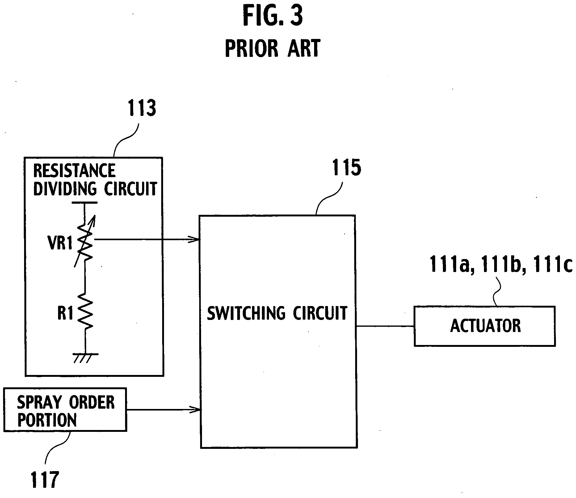
However, when the number of nozzles is larger, it takes a lot of time and trouble to control the volume of the ink-droplet by adjusting the variable resistance VR1 manually.
In fact, when three application heads each having 64 nozzles are mounted in an ink jet application device and then a volume of an ink-droplet is controlled, it takes hours to control the volume of the ink-droplet while it takes a few minutes to apply ink on a substrate.
This makes it more difficult to stably remain quality of a flat display.

Method used


Image

  • Ink jet application device and ink jet application method
  • Ink jet application device and ink jet application method
  • Ink jet application device and ink jet application method

Examples


Embodiment Construction

[0032] In reference with FIGS. 4 to 10, an embodiment of the present invention will be described. Here, an X axis, a Y axis and a Z axis are defined as a longitudinal direction, a width direction and a height direction of an ink jet application device, respectively. The X axis, the Y axis and the Z axis are orthogonal to one another.

[0033] As shown in FIG. 4, an ink jet application device 1 comprises an ink application box 2, an ink supply box 3, a mounting 4, a Y axis direction moving table 5, an X axis direction moving table 6, a pair of columns 7, 7, a slide plate 8, an application head unit 11, a table controller 21, a voltage control unit 31, a spray order portion 41 and a switching circuit 115.

[0034] The ink application box 2 and the ink supply box 3 are fixed on an upper surface of the mounting 4 so as to be adjacent each other. The Y axis direction moving table 5, the X axis direction moving table 6, the columns 7, 7, the slide plate 8 and the application head unit 11 are ...


PUM


Abstract

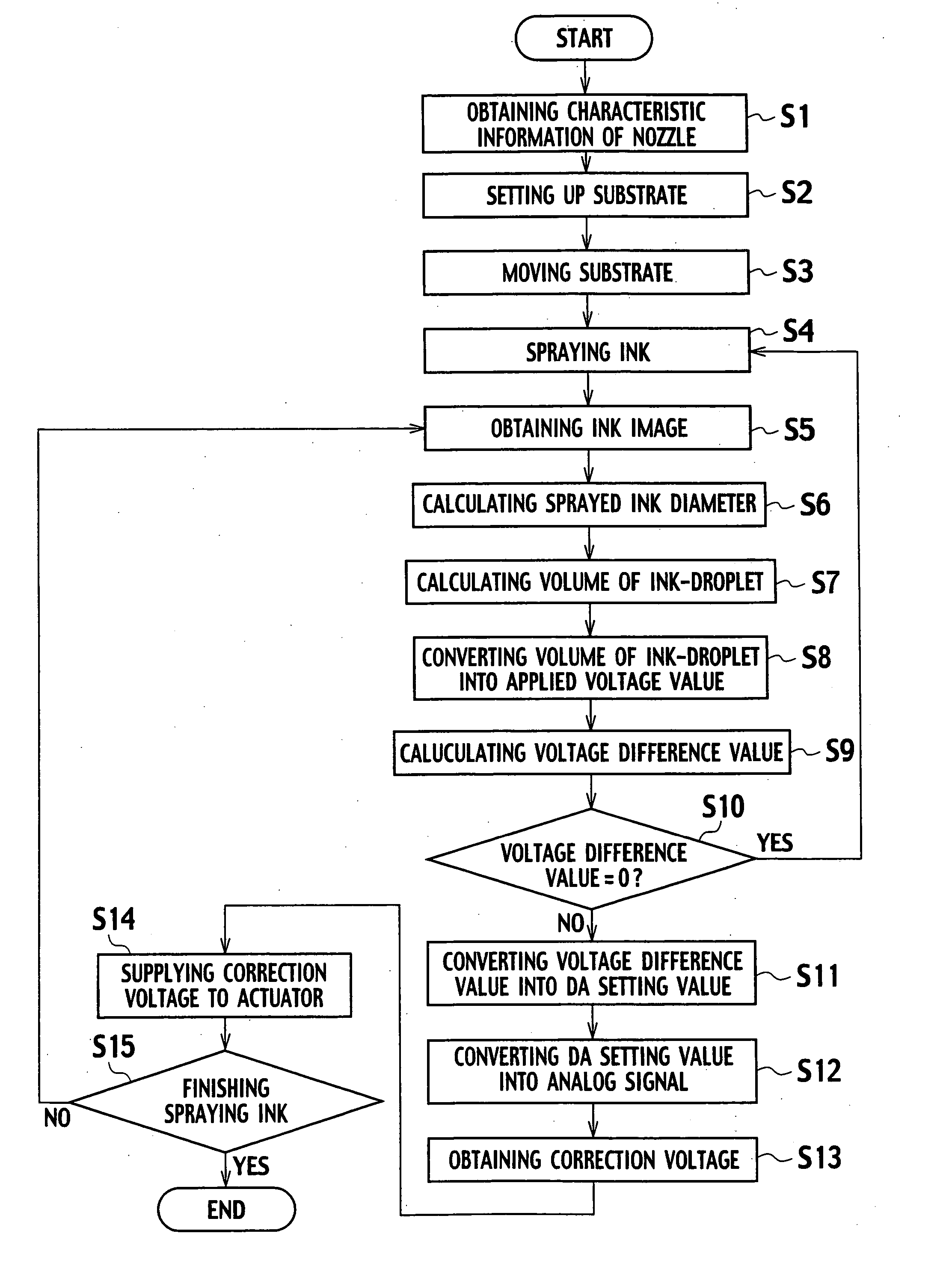
An ink jet application device comprises an application head, an information storage, a first converter, a second converter, a third converter, a three-terminal regulator and a switching circuit. The application head has a plurality of nozzles and a plurality of actuators respectively mounted to the nozzles, and sprays ink from a nozzle by applying a voltage to an actuator. The information storage stores a specific volume of an ink-droplet, characteristic information for relating a volume of the ink-droplet to a voltage value to be applied to the actuator, and setting information for relating a voltage value to be applied to the actuator to a DA setting value. The first converter obtains a volume of the ink-droplet sprayed from a nozzle which is a voltage correcting object, calculates a voltage value related to the volume of the ink-droplet with reference to the characteristic information, and calculates a voltage difference value between the calculated voltage value and a voltage value related to a specific volume of the ink-droplet. The second converter converts the voltage difference value into a DA setting value with reference to the setting information. The third converter converts the DA setting value into an analog signal. The three-terminal regulator outputs a correction voltage when the analog signal is input thereto as a reference voltage. The switching circuit supplies the correction voltage to the actuator mounted to the nozzle which is the voltage correcting object.

Description

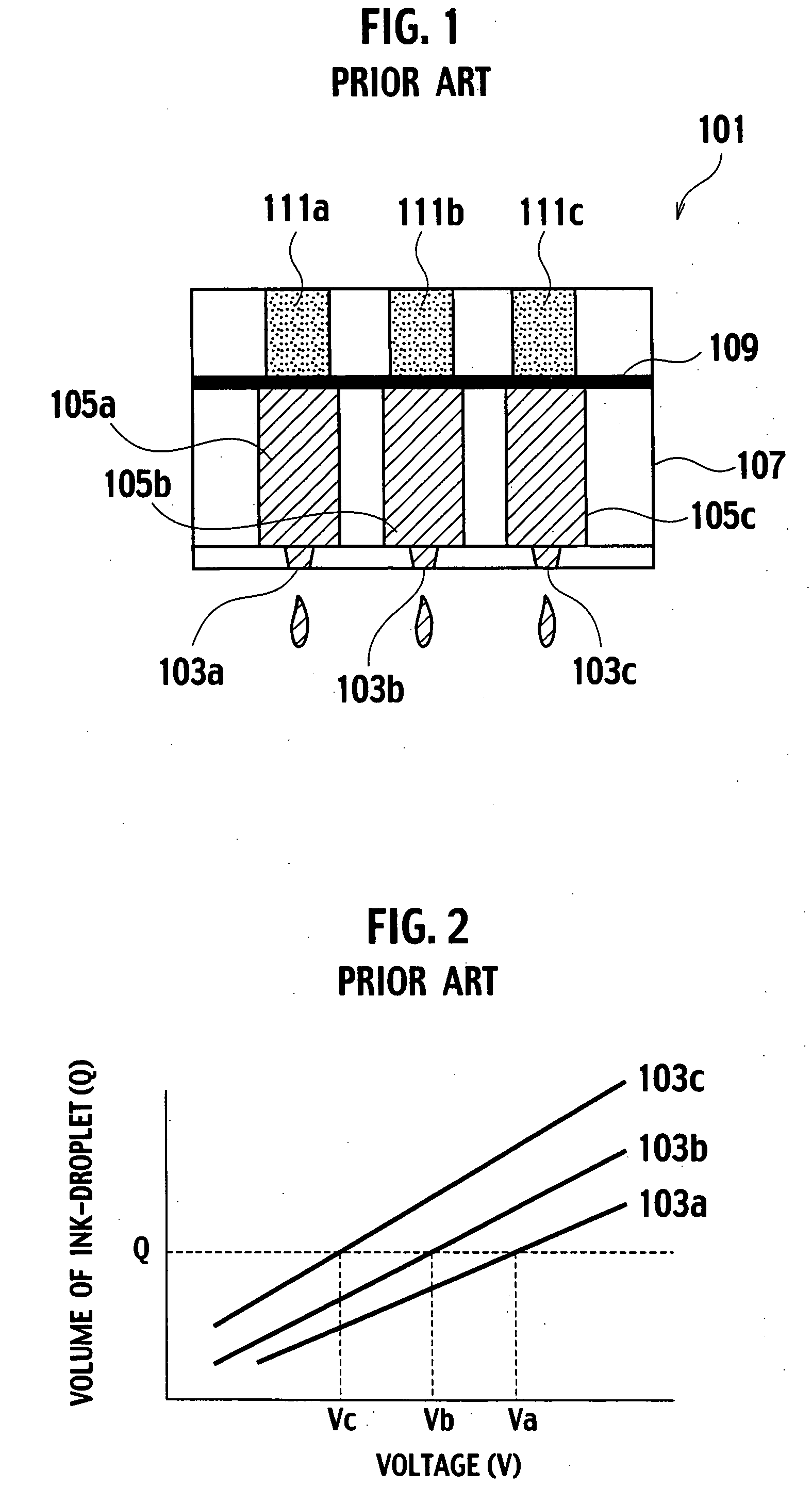
BACKGROUND OF THE INVENTION [0001] 1. Field of the Invention [0002] The present invention relates to an ink jet application device and an ink jet application method for spaying ink-droplets on a substrate. [0003] 2. Description of the Related Art [0004] Recently, a demand for a flat display increases with the development of a personal computer (PC), a portable phone, etc. A liquid crystal display, an organic EL (electro-luminescence) display, etc. are employed as the flat display. In a process for manufacturing the flat display, a luminescent layer material (ink) is applied on a surface of a substrate by an application head mounted in an ink jet application device. [0005] As shown in FIG. 1, an application head 101 comprises nozzles 103a, 103b, 103c, ink chambers 105a, 105b, 105c, a channel unit 107, a diaphragm 109 and actuators 111a, 111b, 111c. The ink chambers 105a, 105b, 105c are communicated with the nozzles 103a, 103b, 103c, respectively. The channel unit 107 accommodates the...

Claims


Application Information

Patent Timeline
Patent Type & Authority Applications(United States)
IPC IPC(8): B41J2/205
CPCB41J2/2128H01L51/0005H01L51/56H10K71/135H10K71/00
Inventor SATO, TSUYOSHIHASEGAWA, YUKIHISAKINASE, ATSUSHI
Owner KK TOSHIBA
Why Eureka
Try Eureka