System and method for load sensing using piezoelectric effect

a piezoelectric effect and load sensing technology, applied in the field of force and strain sensors, can solve the problems of limiting the flexibility of strain gauge-based load measurement, difficulty in attaching strain gauge sensors to objects or components to be measured, and difficulty in reducing the flexibility of application, so as to improve the overall operation efficiency and safety, reduce costly machine downtime, and improve enterprise-wide decision-making, scheduling and productivity.

Inactive Publication Date: 2005-01-20
UNIV OF MASSACHUSETTS
View PDF26 Cites 12 Cited by
  • Summary
  • Abstract
  • Description
  • Claims
  • Application Information

AI Technical Summary

Benefits of technology

[0027] The condition monitoring aspect of the present invention enables integration into a machine component of a static load measurement function that provides accurate, realistic, and quasi real-time loading information for the component being monitored. Such a built-in load measuring technique is useful by way of realizing the next generation “smart” machine components that can self-diagnose their own working conditions for condition-based and predictive maintenance which helps reduce costly machine down-time and improve enterprise-wide decision making, scheduling, and productivity.
[0028] In addition to monitoring loading status on individual machine components, the present invention provides an integrated static load measurement system which can serve as a “smart” built-in monitor that oversees an entire machine system (e.g., multi-axis machine centers, power generators, off-highway trucks, excavators, railway trains or airplanes) or a manufacturing process (e.g., assembly line, chemical process, natural gas production, or oil refinery), thus improving the overall operation efficiency and safety.

Problems solved by technology

Strain gauge-based load measurement, however, has a number of drawbacks.
Such a requirement severely limits the flexibility of their applications in many manufacturing-related scenarios where space is restricted.
Another disadvantage of strain gauge-based load measurement is the difficulty in attaching the strain gauge sensors to an object or component to be measured.
Such glues have a limited fatigue life, and are sensitive to temperature variations.
Such a requirement increases the cost and space needed.
These drawbacks make it impractical and very difficult for strain gauges to be effectively integrated into a realistic machine environment for on-line, in-process static load measurement, especially under space constraints.
However, because of the inherent problem of charge leakage resulting and the subsequent loss of information due to the non-infinite insulation resistance of the piezoelectric sensors, it has been traditionally considered impossible to use piezoelectric sensors for pure static load measurement.

Method used


Image

  • System and method for load sensing using piezoelectric effect
  • System and method for load sensing using piezoelectric effect
  • System and method for load sensing using piezoelectric effect

Examples


example 1

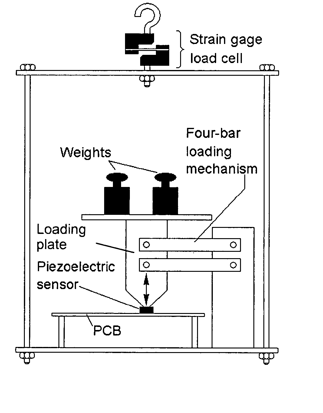
[0081] As illustrated in FIG. 6, a piezoelectric sensor system in accordance with this invention, was mounted on a printed circuit board (PCB). The sensor itself was subject to the force application by means of standard weights, through a four-bar rectangular planar mechanism, which constrained the motion of the scale plate holding the weights to a vertical linear displacement. The plate supporting the PCB and the four-bar mechanism was suspended by wires. For comparison and reference purpose, a strain gage load cell of the prior art was installed along the suspension hook. Due to the series mechanical connection, the strain gage load cell measured the same load as the piezoelectric sensor, thus realizing a “back-to-back” calibration basis. Output signals from the two load measuring systems (strain gage and piezoelectric sensor) are comparatively shown on the plots that follow.

[0082] The strain gage circuit was first calibrated using standard weights before the experiment. As a res...

example 2

[0087] Constant Load Test

[0088] The plots of FIG. 7 shows the circuit output when weights of 200 g (left) and 500 g (right) were applied to the sensor. The piezoelectric sensor (middle) was able to deliver a constant voltage output corresponding to the weight applied. The output is comparable to that of the strain gage sensor (top). The bottom portion of the figure illustrates the circuit trigger.

example 3

[0089] Toggled Load Test

[0090] The toggled load tests were aimed at demonstrating the repeatability of the measurement using the inventive piezoelectric sensor / system.

[0091] As seen in FIG. 8, the piezoelectric circuit has shown good repeatability when known weights (220 g, left, and 400 g, right) were repeatedly placed on the sensor, taken away, and then put back on again. Comparing to the strain gage circuit output, the piezoelectric sensor has shown less to much less spikes at the load-unload interfaces.


PUM

PropertyMeasurementUnit
voltageaaaaaaaaaa
output voltageaaaaaaaaaa
frequencyaaaaaaaaaa

Abstract

System and method for measuring static load by using a piezoelectric load sensor with a feedback technique to compensate for the signal loss due to charge leakage, and therefore ensures measurement accuracy. The system is integrated with other structure, objects and devices to measure static loads applied to a mechanical shaft, in an on-line, in-process, quasi real-time fashion. The system can be used to measure static load and thus oversee an entire machine system or a manufacturing process.

Description

[0001] This application claims priority benefit from provisional application Ser. No. 60 / 477,263 filed Jun. 10, 2003, the entirety of which is incorporated herein by reference.[0002] The United States government has certain rights to this invention pursuant to Grant No. DMI-9624353 from the National Science Foundation to The University of Massachusetts.BACKGROUND OF THE INVENTION [0003] The present invention relates generally to force and strain sensors; more particularly to a system and method of measuring static load using the piezoelectric effect with a feedback technique to compensate for signal loss. [0004] Static load measurement is widely used in industrial and commercial applications, from machine tools to transportation systems (e.g., trains, forklifts, trucks, cranes) to scales for postal, freight, or personal weighting purposes. [0005] Various physical principles have been explored over the past few decades for static load measurement, resulting in sensors that either mak...

Claims


Application Information

Patent Timeline
Patent Type & Authority Applications(United States)
IPC IPC(8): G01G3/13G01N3/08H01L
CPCG01G3/13
Inventor GAO, ROBERT X.SOVENYI, SZABOLCS
Owner UNIV OF MASSACHUSETTS
Why Eureka
Try Eureka