
Development apparatus

a technology of development apparatus and development plate, which is applied in the direction of electrographic process apparatus, instruments, optics, etc., can solve the problems of irregular density in printing, inability of conventional developer detection mechanism to convey toner to a lateral direction, and inability to detect the remaining amount of toner, so as to prevent irregular image density and stable uniform operation , the effect of stable uniform operation

Active Publication Date: 2006-08-24
SHARP KK
View PDF12 Cites 29 Cited by
  • Summary
  • Abstract
  • Description
  • Claims
  • Application Information

AI Technical Summary

Benefits of technology

[0014] According to the development apparatus of the present invention, the auger conveyor member of stirring and conveying a developer, the gravity of the developer being eccentrically distributed with respect to a center of rotation, the drive transfer member of driving and rotating the auger conveyor member, the drive transfer member being capable of being engaged and disengaged, and the rotation detector of detecting a rotational state of the auger conveyor member are provided. Thereby, the powder pressure of the developer in a development tank is made uniform, and a surface of the toner is consistently made flat, resulting in maintenance of satisfactory image quality and high-precision detection of the remaining amount of the developer.
[0046] An effect of the second development apparatus of the present invention described above can be exhibited to a further extent when the development apparatus is not provided with a replenishing roller of controlling the replenished amount of a developer in the development tank. When the developer is made of a single non-magnetic component, the effect of the second development apparatus is exhibited to a further extent. A two-component developer including a carrier can prevent blocking of the developer due to the carrier. Therefore, the function and effect of the uniforming member in the second development apparatus are more effectively exhibited when the development agent is made of a single non-magnetic component.

Problems solved by technology

Therefore, the toner of the toner tank 900 is consumed in the middle portion thereof more than in both edge portions thereof, so that the toner level in the toner tank 900 becomes uneven as a whole, leading to occurrence of irregular density in printing.
Thus, the conventional developer detecting mechanism does not have an ability to convey the toner to a lateral direction.
Therefore, when there occurs an extreme difference in the toner level between the middle portion and the edge portion of the toner tank 900, an error may occur in detection of the toner remaining amount and the detection accuracy may be insufficient.

Method used


Image

  • Development apparatus
  • Development apparatus
  • Development apparatus

Examples


example 1

[0065] Explanation of Whole Image Forming Apparatus

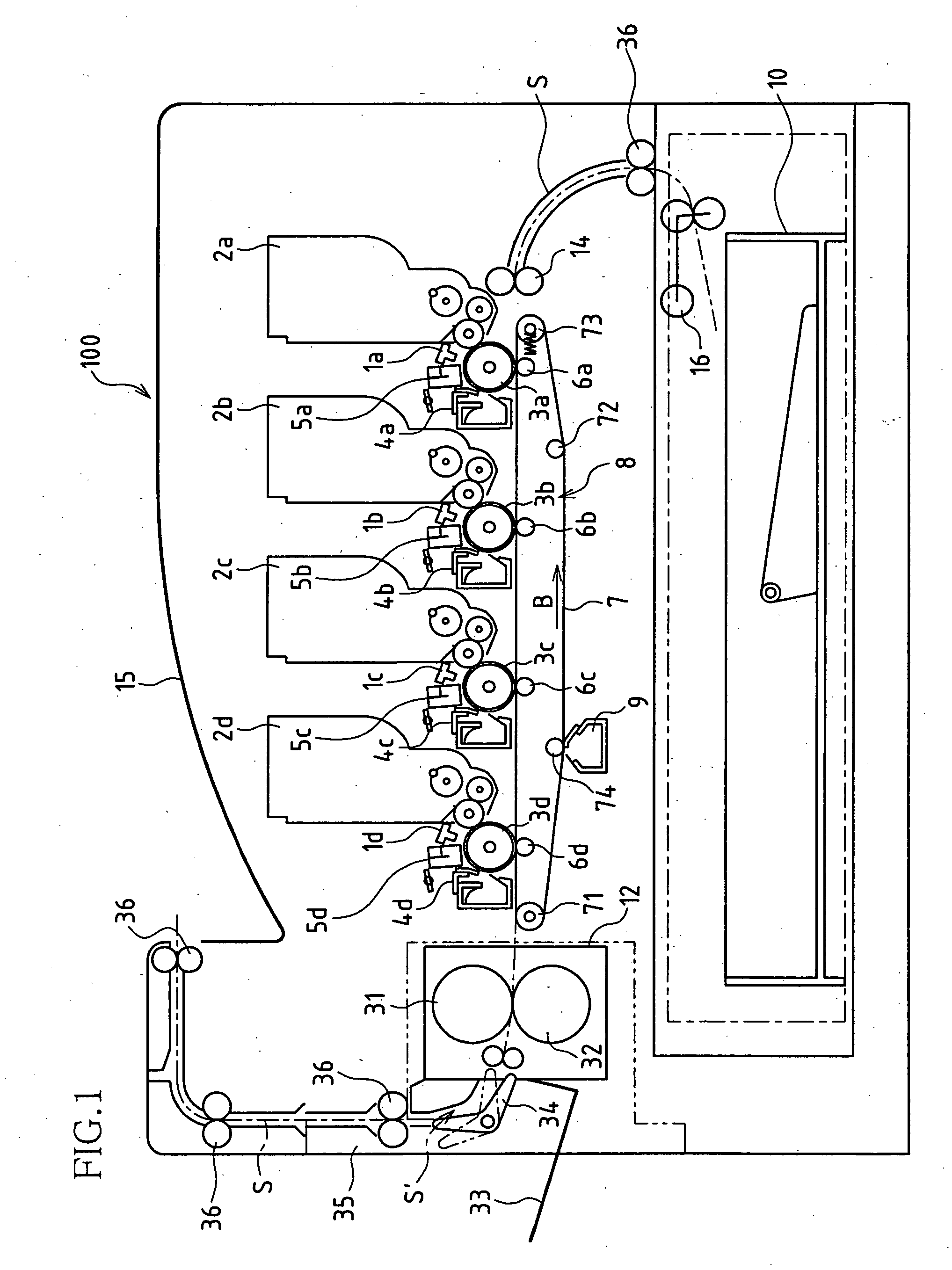
[0066]FIG. 1 is a cross-sectional view schematically illustrating a structure of a digital color photocopying machine (hereinafter simply referred to as a copier) 100 as a color image forming apparatus according to Example 1 of the present invention.

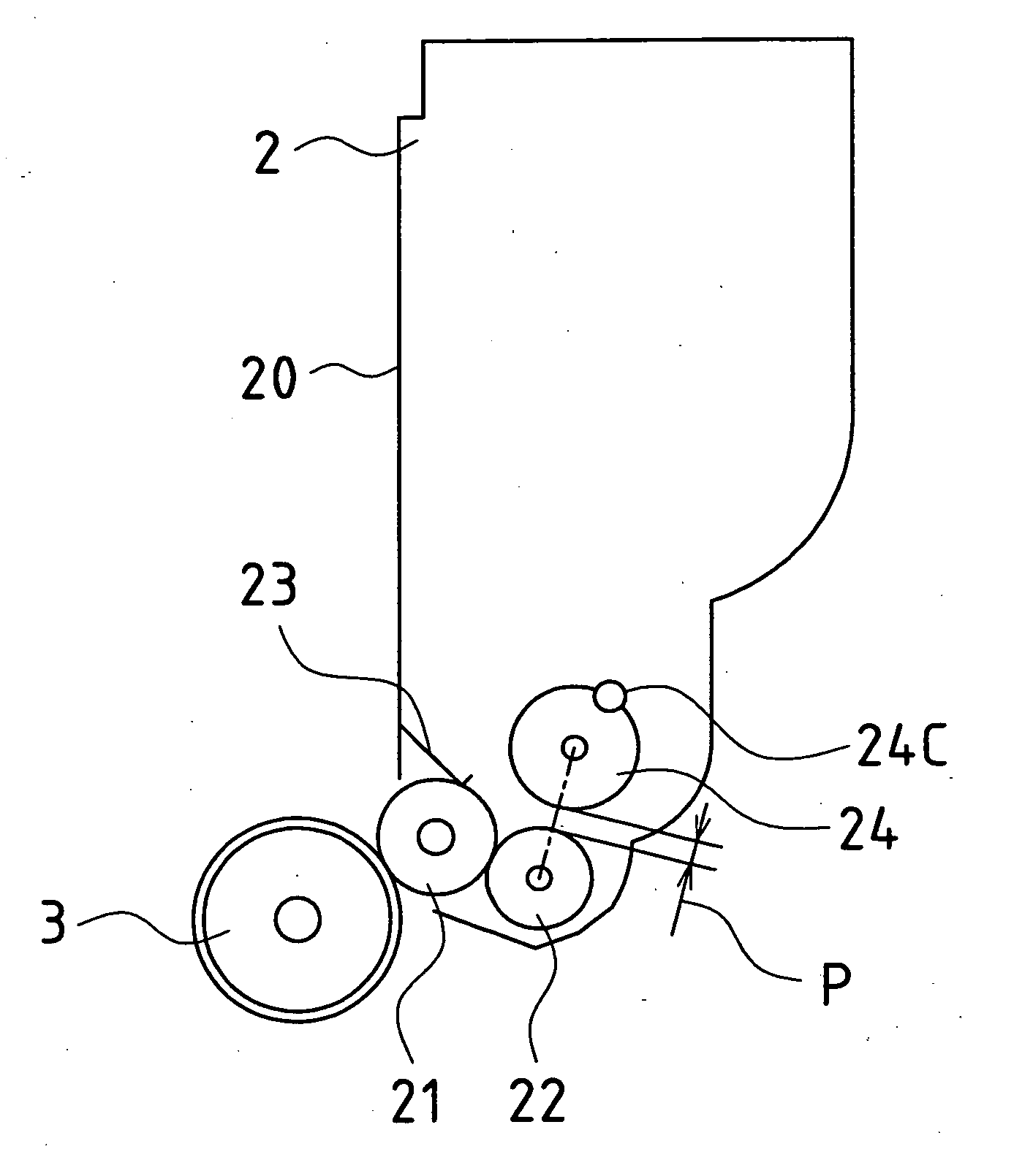
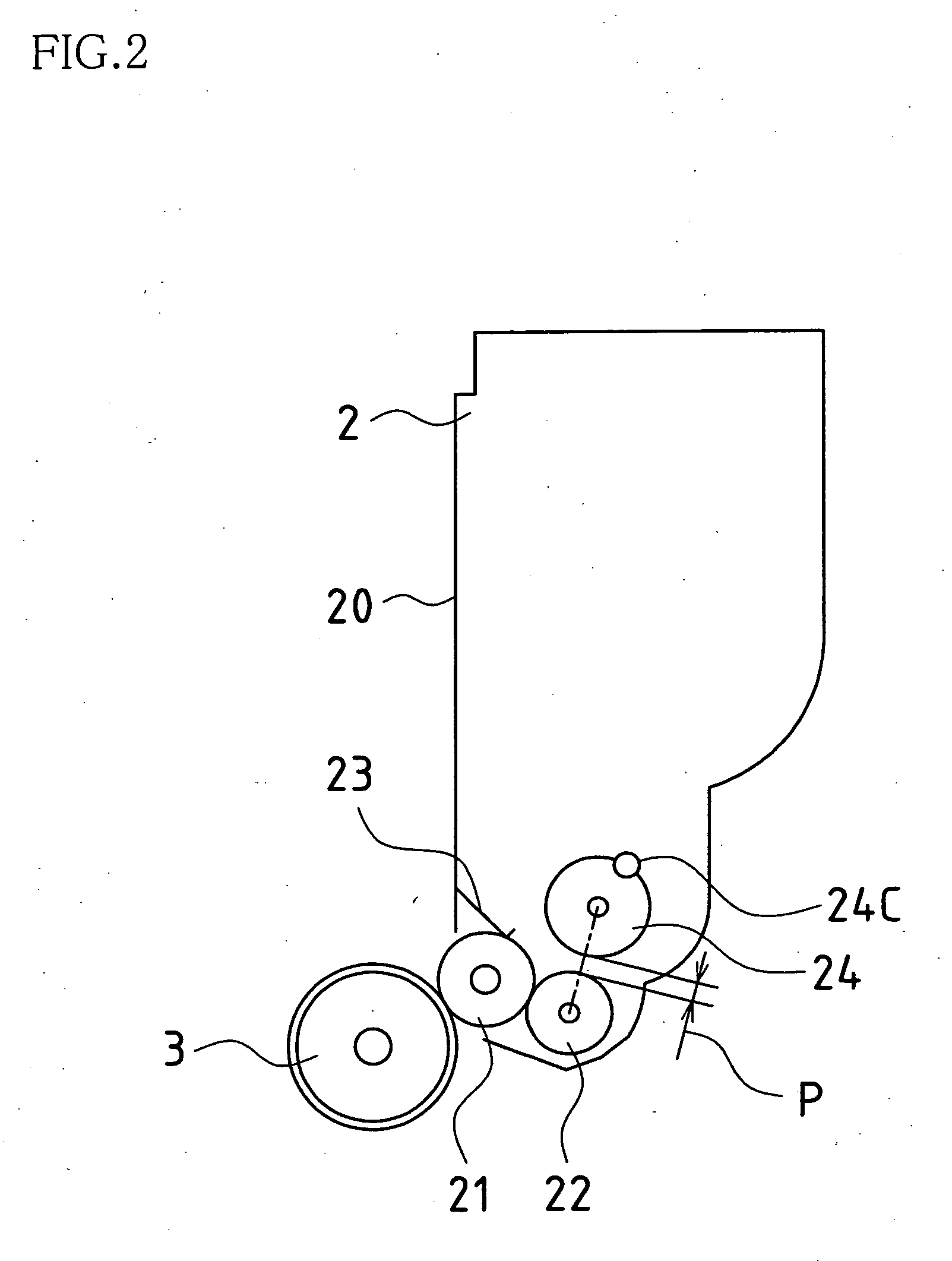
[0067] The copier 100 forms a multicolor or monocolor image on a predetermined sheet (recording paper) in accordance with externally input image data. The copier 100 is composed of an exposure unit 1, a development apparatus 2, a photoconductive drum 3, an electrifier 5, a cleaner unit 4, a transfer conveying belt unit 8, a fixing unit 12, a paper conveying path S, a paper feed tray 10, paper output trays 15 and 33, and the like.

[0068] The copier 100 processes image data corresponding to a color image having black (K), cyan (C), magenta (M), and yellow (Y) colors. Therefore, the exposure unit 1 (1a, 1b, 1c, 1d), the development apparatus 2 (2a, 2b, 2c, 2d), the photoconductive drum 3 ...

example 2

[0109] Next, a development apparatus which has a form different from that of Example 1 will be described with reference to the accompanying drawings. Note that the development apparatus of Example 2 has the same structure as that of Example 1, except for the development apparatus 2 and the developer detecting mechanism section of Example 1. Therefore, in Example 2, the same parts as those of the developer detecting mechanism section of Example 1 are indicated with the same reference numerals and will not be explained. A function and an effect different from those of Example 1 will be described, and the same function, effect, and variation will not be explained.

[0110]FIGS. 9 and 10 are diagrams for explaining a structure of a developer detecting mechanism section of a development apparatus 2 according to Example 2 of the present invention.

[0111] The developer detecting mechanism section has the above-described auger conveyor roller 24, and in addition, a single second auger conveyo...

example 3

[0112] Next, a development apparatus which has a form different from that of Example 1 will be described with reference to the accompanying drawings. Note that the development apparatus of Example 3 has the same structure as that of Example 1, except for the development apparatus 2 and the developer detecting mechanism section of Example 1. Therefore, in Example 3, the same parts as those of the developer detecting mechanism section of Example 1 are indicated with the same reference numerals and will not be explained. A function and an effect different from those of Example 1 will be described, and the same function, effect, and variation will not be explained.

[0113]FIGS. 11 and 12 are diagrams for explaining a structure of a developer detecting mechanism section of the development apparatus 2 according to Example 3 of the present invention.

[0114] The developer detecting mechanism section is in the shape of a crank, in which a stainless steel shaft 101 (outer diameter: 4 mm, herei...


PUM


Abstract

A development apparatus comprises an auger conveyor member of stirring and conveying a developer, the gravity of the developer being eccentrically distributed with respect to a center of rotation, a drive transfer member of driving and rotating the auger conveyor member, the drive transfer member being capable of being engaged and disengaged, and a rotation detector of detecting a rotational state of the auger conveyor member. The remaining amount of the developer is detected based on the rotational state detected by the rotation detector. Alternatively, a development apparatus comprises the auger conveyor member and the drive transfer member, in which the eccentric gravity distribution is achieved by a rod-like weight member eccentrically provided with respect to a rotational axis, the auger conveyor member includes a first coil spring having an inner diameter larger than an outer diameter of the weight member, and the first coil spring is inserted around the weight member in a manner which allows the first coil spring to be rotated and limits an angle of rotation of the first coil spring to a predetermined angle. Alternatively, a development apparatus comprises the auger conveyor member and the drive transfer member, in which the auger conveyor member is provided near a development supply roller, and a uniforming member of making the developer uniform is provided in a space portion between the development supply roller and the auger conveyor member.

Description

BACKGROUND OF THE INVENTION [0001] This application claims priority under 35 U.S.C. § 119(a) on Patent Application No. 2004-207459 filed in Japan on Jul. 14, 2004, Patent Application No. 2004-244136 filed in Japan on Aug. 24, 2004, Patent Application No. 2004-284795 filed in Japan on Sep. 29, 2004, and Patent Application No. 2004-309846 filed in Japan on Oct. 25, 2004, the entire contents of which are hereby incorporated by reference. [0002] The present invention relates to a development apparatus having a function to detect the remaining amount of a developer remaining in a development tank. [0003] Development apparatuses need to be replaced with new ones when a developer is exhausted in a development tank. Therefore, the development apparatus is provided with a developer detecting mechanism for detecting the remaining amount of the developer held in the development tank. [0004] As a technique relating to such a developer detecting mechanism, a developer detecting mechanism illustr...

Claims


Application Information

Patent Timeline
IPC IPC(8): G03G15/08
CPCG03G15/0856G03G15/0891G03G15/0858
Inventor TAKESAWA, YOHICHIHAYASHI, SHIGEKIKIDO, EIICHINISHINO, TOSHIO
Owner SHARP KK
Learn More