
Stent retrieval member and devices and methods for retrieving or repositioning a stent

a technology for stents and stents, applied in the field of devices, methods and systems for retrieving and/or repositioning of implanted stents, can solve problems such as difficulty in grabbing a hook or lasso

Active Publication Date: 2006-08-24
BOSTON SCI SCIMED INC
View PDF14 Cites 143 Cited by
  • Summary
  • Abstract
  • Description
  • Claims
  • Application Information

AI Technical Summary

Benefits of technology

[0009] The present invention provides a stent retrieval system that allows for easy access to the retrieval member located on an implantable stent. Further, the stent removal member of the present invention avoids complicated twisting movements for retrieval or repositioning of the implanted stent.

Problems solved by technology

Moreover, in smaller stents, such as biliary stents, the spacing between conventional stent segments is generally smaller than the size of standard forceps or graspers, making it even difficult to grab a hook or lasso.

Method used


Image

  • Stent retrieval member and devices and methods for retrieving or repositioning a stent
  • Stent retrieval member and devices and methods for retrieving or repositioning a stent
  • Stent retrieval member and devices and methods for retrieving or repositioning a stent

Examples


Embodiment Construction

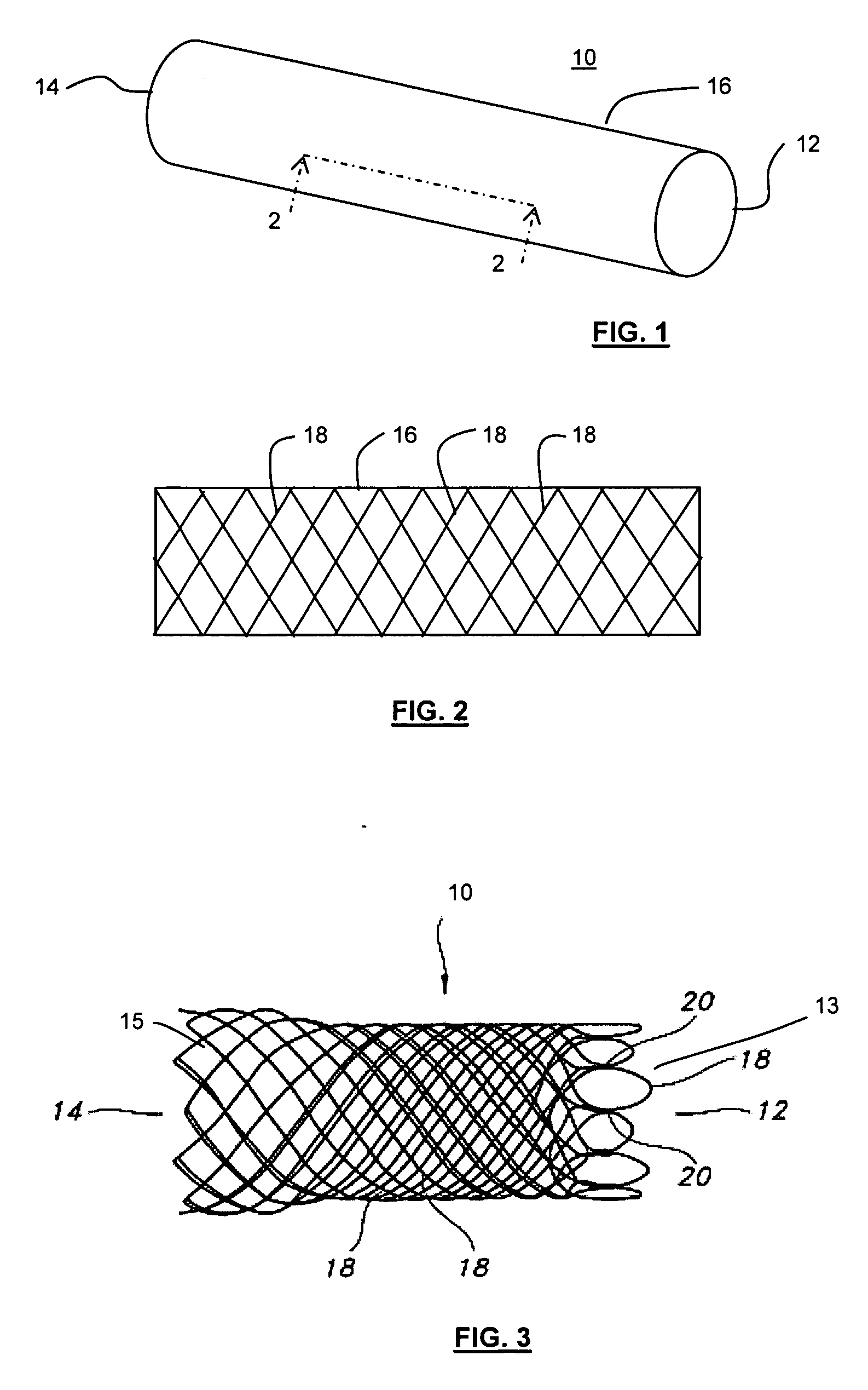
[0036]FIG. 1 depicts stent 10 of the present invention. Stent 10 is a hollow tubular structure having opposed open ends 12, 14 and having a tubular wall 16 therebetween. A portion of the tubular wall 16 is depicted in FIG. 2 as having a plurality of elongate wires 18 formed into the tubular wall 16. The elongate wires 18 traverse the length of the stent 10 in a direction traverse to the longitudinal length of the stent 10. The elongate wires 18 may be formed into the tubular wall 16 by braiding the wires 18, winding the wires 18, knitting the wires 18, and combinations thereof. Preferably, the wires 18 are braided to form the tubular wall 16.

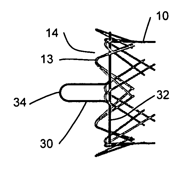
[0037] As depicted in FIG. 3, stent 10 is desirably an atraumatic stent having no sharp terminating members at one or both of the opposed open ends 12, 14. The elongate wires 18 terminating at open end 12 are mated to form closed loops 13 and adjacently mated wires are secured to one and the other by mechanical means, such as welds 20. The posi...


PUM


Abstract

An implantable stent includes a stent retrieval member for repositioning or retrieval of the stent after it has been implanted into a bodily lumen. The stent includes a distensible tubular stent having a tubular structure having a tubular wall defined by an interior surface and an exterior surface and having opposed open ends; and a stent retrieval member comprising an elongate member comprising a generally circular perimetric base and a shaped projection having first and second spaced apart members extending acutely or perpendicularly from the base and connected by an apical portion. Force exerted on the shaped projection causes contraction or expansion of the circular base. The circular base is securably attached to one of the open ends of the stent, and the shaped projection extends longitudinally beyond this open end of the stent.

Description

CROSS-REFERENCE TO RELATED APPLICATIONS [0001] This application claims the benefit of U.S. Provisional Application No. 60 / 647,981, filed Jan. 28, 2005, the contents of which are incorporated herein by reference.FIELD OF THE INVENTION [0002] The present invention relates to devices, methods and systems for retrieval and / or repositioning of an implanted stent. More particularly, the present invention relates to implantable stents having a stent retrieval member or loop for easy for retrieval and / or repositioning of the implanted stent. BACKGROUND OF THE INVENTION [0003] An intraluminal prosthesis is a medical device used in the treatment of diseased bodily lumens. One type of intraluminal prosthesis used in the repair and / or treatment of diseases in various body vessels is a stent. A stent is a generally longitudinal tubular device formed of biocompatible material which is useful to open and support various lumens in the body. For example, stents may be used in the vascular system, ur...

Claims


Application Information

Patent Timeline
Patent Type & Authority Applications(United States)
IPC IPC(8): A61F2/06A61F2/90
CPCA61F2/885A61F2/90A61F2/95A61F2002/9511A61F2002/9528A61F2002/9534A61F2250/0039A61F2210/0014A61F2210/0057A61F2230/0069
Inventor JORDAN, GARY A.CLERC, CLAUDE O.NORTON, PAUL K.ZUPKOFSKA, MICHAELDAMARATI, JOHN J.
Owner BOSTON SCI SCIMED INC
Features
  • Generate Ideas
  • Intellectual Property
  • Life Sciences
  • Materials
  • Tech Scout
  • Unparalleled Data Quality
  • Higher Quality Content
  • 60% Fewer Hallucinations
Learn More