

Electronic compass and direction finding method
a technology of electronic compass and direction finding, applied in surveying and navigation, navigation instruments, instruments, etc., can solve the problems of long time for displaying method takes a long time to display a relatively accurate direction, and directions including enormous errors (or intelligible directions) will be displayed for a long time. to achieve the effect of freeing a driver from uneasiness
- Summary
- Abstract
- Description
- Claims
- Application Information
AI Technical Summary
Benefits of technology
Problems solved by technology
Method used
Image

Examples
first preferred embodiment
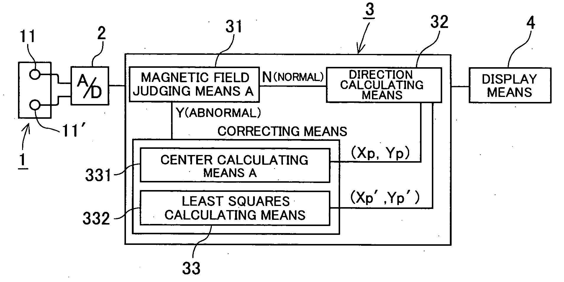
[0054] An electronic compass of this preferred embodiment comprises, as shown in FIG. 3, a geomagnetic direction sensor 1 having a pair of magnetic sensor elements 11, 11′ which are sensor bars arranged perpendicular to each other and detect an X component and a Y component of the Earth's magnetic field vector as two-dimensional Cartesian coordinate data (X1, Y1), (X2, Y2) . . . (Xi, Yi); an A / D converter which converts outputs from the magnetic sensor elements 11, 11′ into digital signals at a predetermined period frequency; a microcomputer 3 which calculates a heading direction of a mobile object from the inputted digital signals in software; and a display means 4 for displaying the calculated direction.
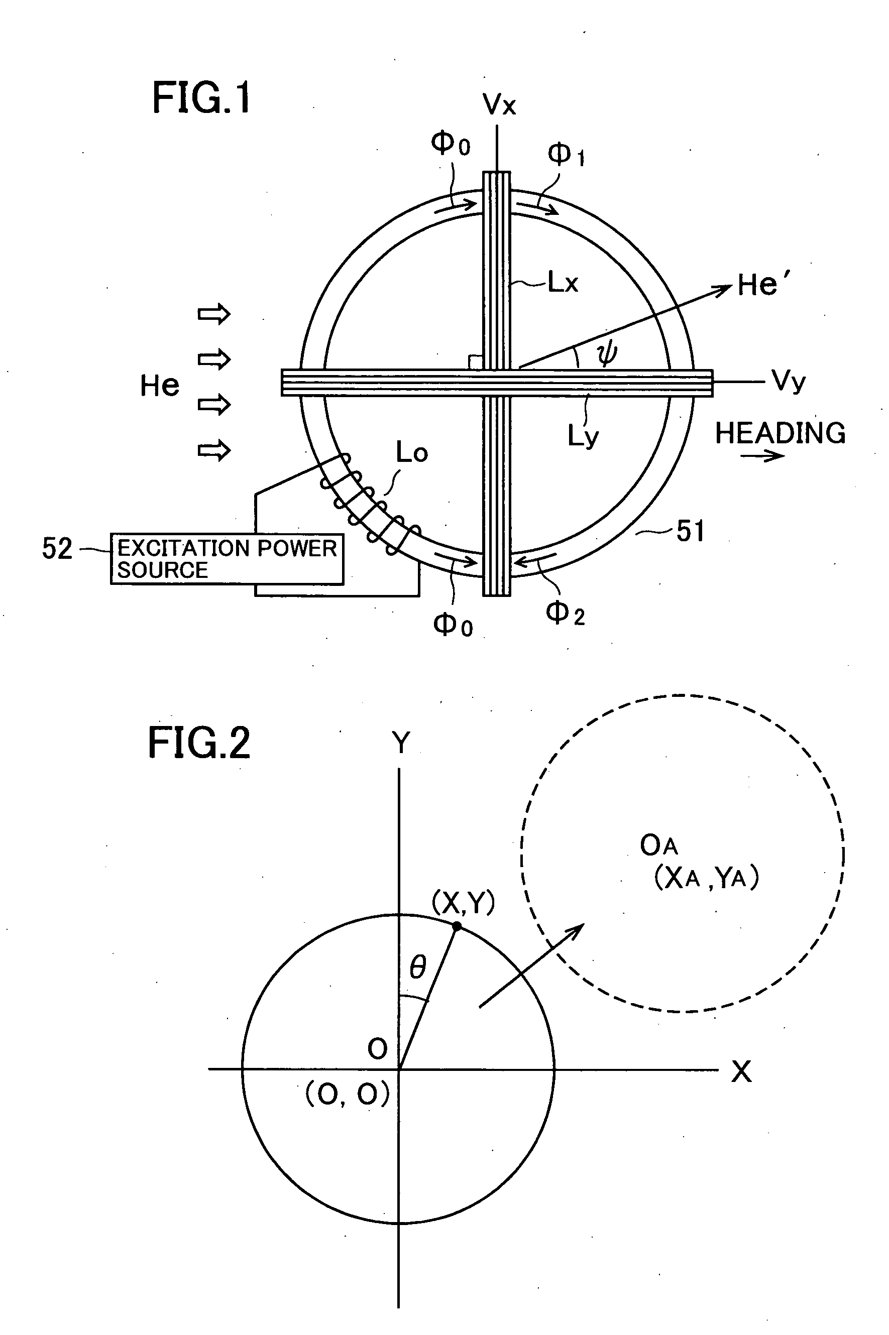
[0055] It is possible to employ, as the geomagnetic direction sensor 1, the conventional sensor which uses two coils wound orthogonally around a permalloy core as the magnetic sensor elements 11, 11′, as shown in FIG. 1. However, it is preferable to employ a magnetic sensor which ...
second preferred embodiment
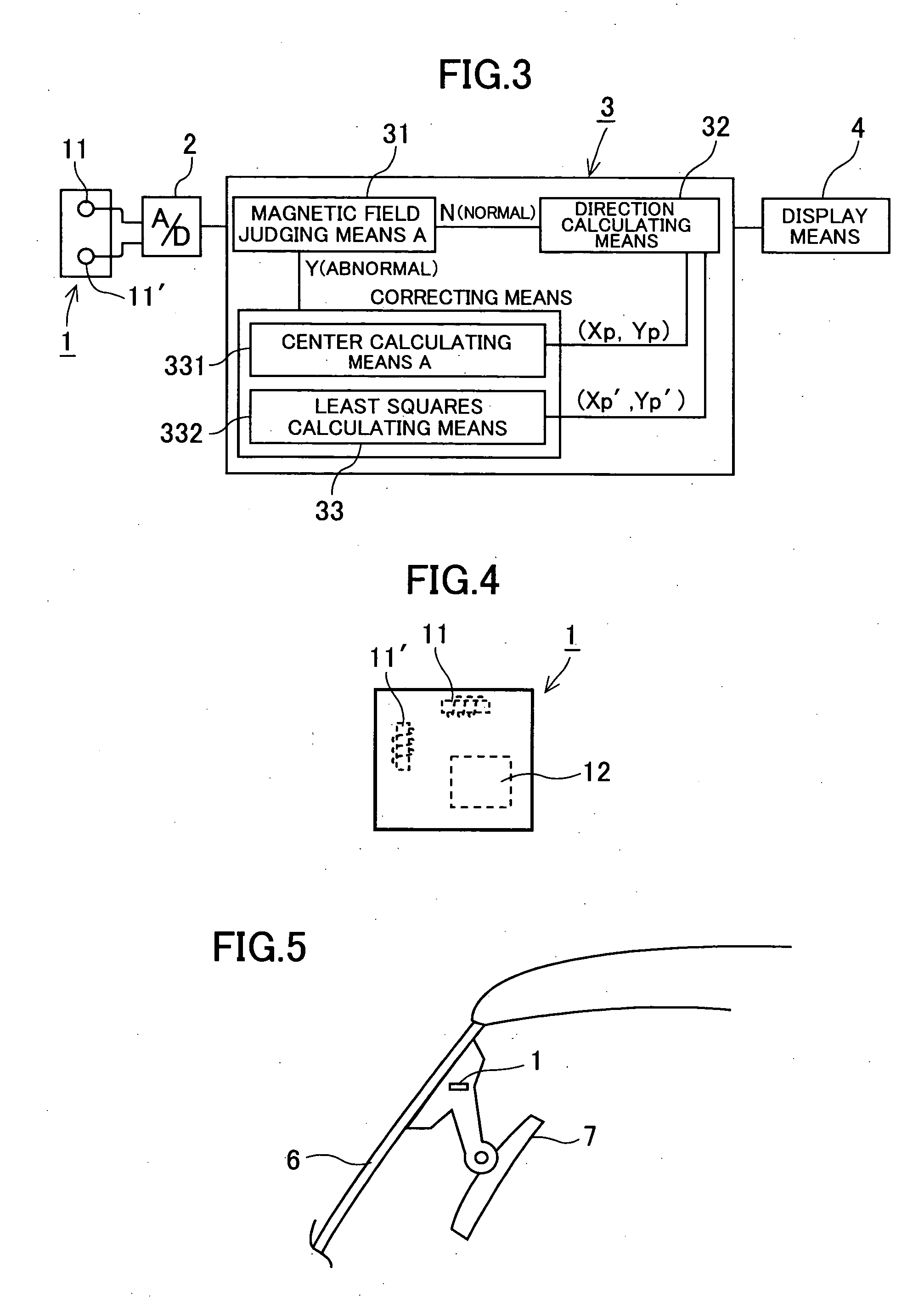
[0074] An electronic compass of this preferred embodiment is similar to that of the first preferred embodiment, except for the microcomputer, as shown in FIG. 9. A microcomputer 3″ of this preferred embodiment comprises a direction calculating means 32 for calculating a heading direction θ of a mobile object, a magnetic field judging means B 31′ for receiving the heading direction θ from the direction calculating means 32 and determining whether the magnetic field is normal or abnormal, and a correcting means 33″ for correcting the center of the azimuth circle when the magnetic field judging means B 31′ determines that the magnetic field is abnormal. The correcting means 33″ has a center calculating means B 331′ and a least squares calculating means 332. It is to be noted that the magnetic field judging means B 31′, the direction calculating means 32 and the correcting means 33″ are software components. The same components as those of the first preferred embodiment are designated by...
PUM
 Abstract
Description
Claims
Application Information