Supercharge Your Innovation With Domain-Expert AI Agents!

Particulate trap regeneration control system

Inactive Publication Date: 2006-08-31
CATERPILLAR INC
View PDF22 Cites 27 Cited by
  • Summary
  • Abstract
  • Description
  • Claims
  • Application Information

AI Technical Summary

Benefits of technology

[0009] One aspect of the present disclosure includes a regeneration control system for an exhaust element. The regeneration control system may include one or more filter sections within the exhaust element. The regeneration control system may also include a controller configured to determine an amount of soot accumulated in the exhaust. The controller may also be configured to determine an amount of ash accumulated in the exhaust element. The controller may also be configured to determine the accumulated particulate matter in the exhaust element based on the accumulated soot and the accumulat

Problems solved by technology

Engines, including diesel engines, gasoline engines, natural gas engines, and other engines in the art, may exhaust air pollutants.
Particulate matter trapped by the filter can accumulate in the filter and reduce the operating efficiency of the engine.
Therefore, the engine may consume more fuel to produce the same amount of power as compared to when the filter is free of particulates.
Because the need for regeneration is related to the amount of particulate matter accumulated in the exhaust element, and because the pressure differential measurement method of the '480 patent may be inadequate for accurately determining the amount of particulate matter accumulated in the exhaust element, the method of the '480 patent may be unsuited for accurately determining when to regenerate.

Method used


Image

  • Particulate trap regeneration control system
  • Particulate trap regeneration control system
  • Particulate trap regeneration control system

Examples


Embodiment Construction

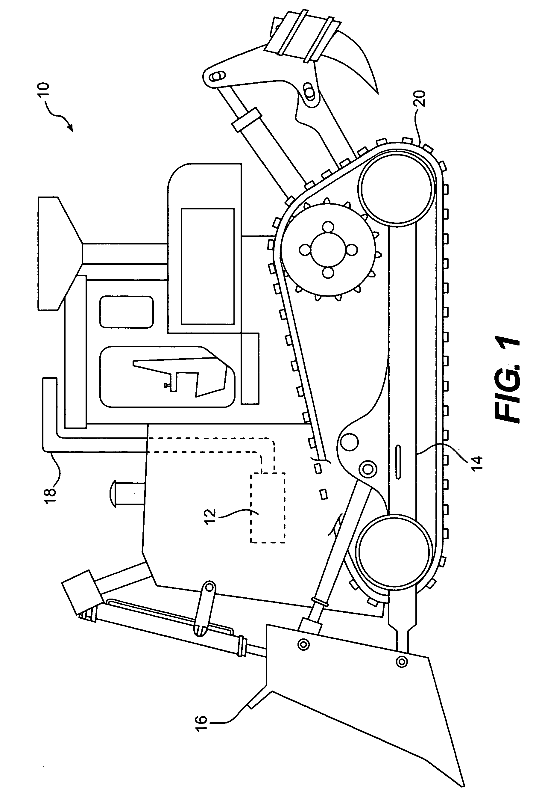
[0014]FIG. 1 provides a pictorial illustration of a work machine 10. Work machine 10 may include engine 12. Work machine 10 may also include a frame 14 and a work implement 16. Engine 12 may be operably connected to an exhaust system 18. Engine 12 may include a diesel engine, a gasoline engine, or any other power-producing device. Work machine 10 may also include a traction device 20.

[0015] While work machine 10 is shown as a track type tractor, work machine 10 may include various types of machines. For example, work machine 10 may be a truck, wheeled tractor, dump truck, automobile, on-highway vehicle, off-highway vehicle, skid-steer, stationary generator, or any other device that includes an engine that generates an exhaust stream.

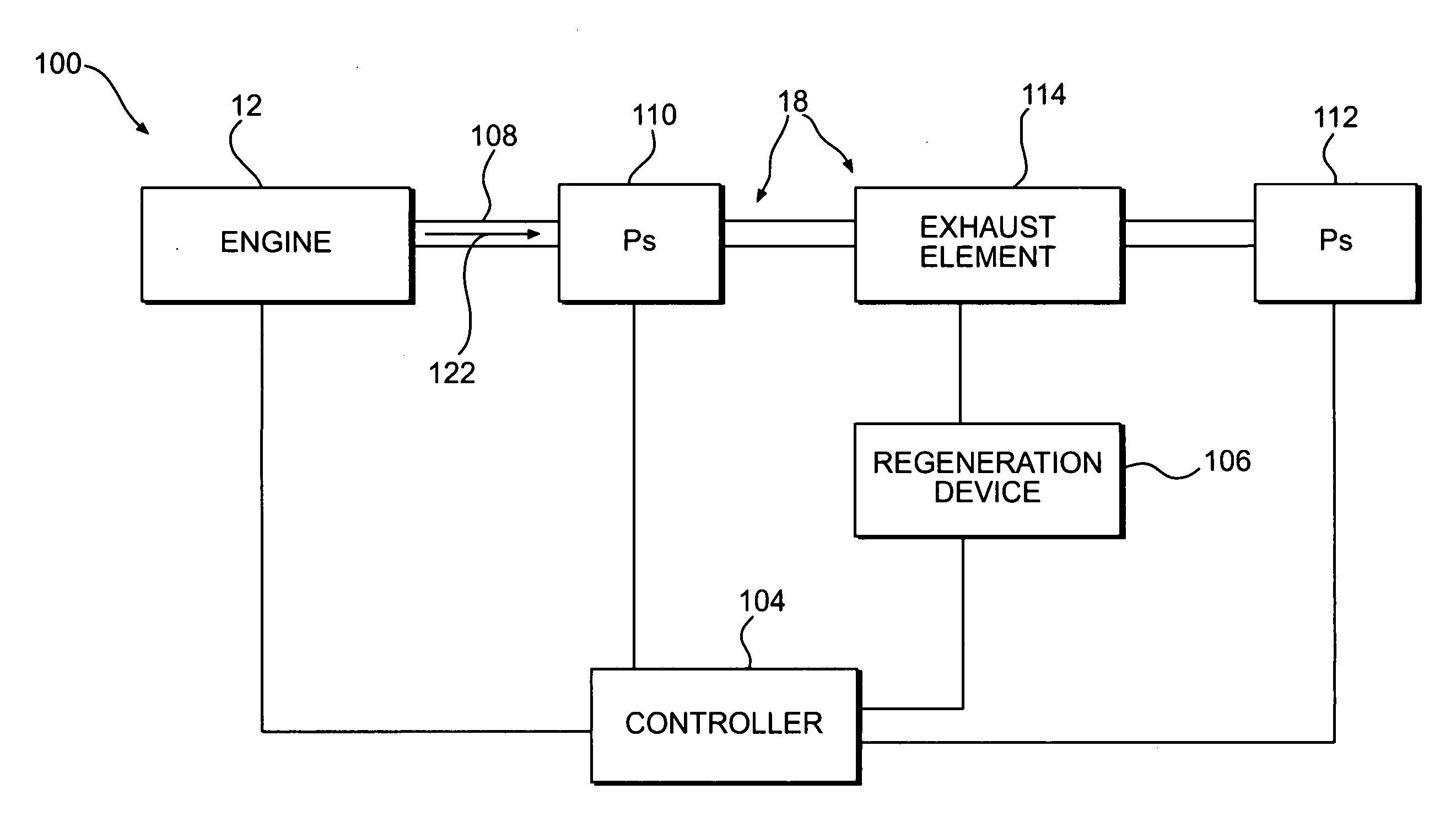
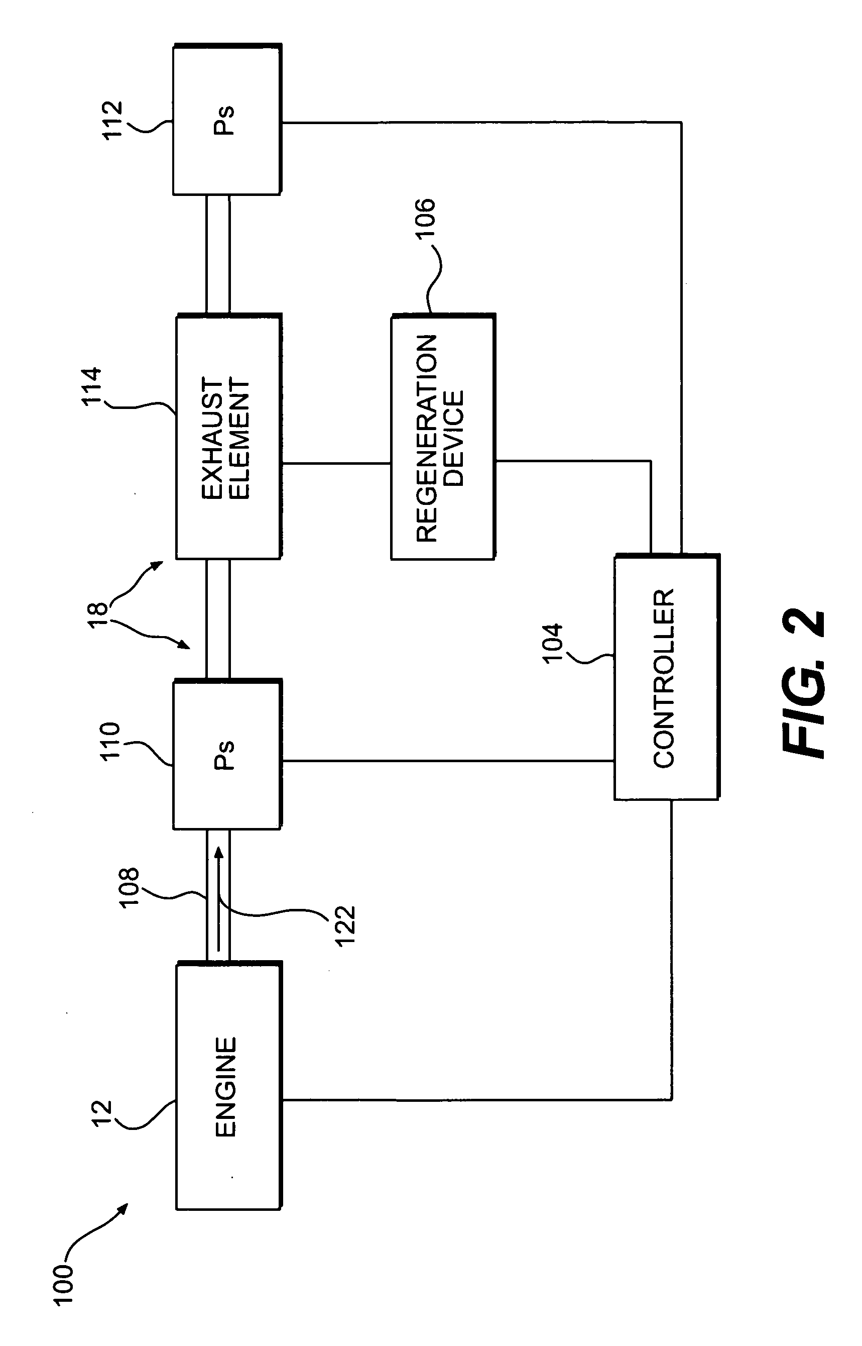
[0016] Exhaust system 18 may include components used to transfer exhaust produced by engine 12 or other exhaust producing devices to the atmosphere. For example, exhaust system 18 may include an exhaust manifold (not shown), a particulate filter or any...


PUM


Abstract

A particulate trap regeneration control system may include one or more filter sections within the exhaust element. The regeneration control system may also include a controller configured to determine an amount of soot accumulated in the exhaust. The controller may also be configured to determine an amount of ash accumulated in the exhaust element. The controller may also be configured to determine the accumulated particulate matter in the exhaust element based on the accumulated soot and the accumulated ash in the exhaust element.

Description

TECHNICAL FIELD [0001] The present disclosure is directed to controlling regeneration of exhaust system components and, more particularly, to systems and methods for regenerating exhaust system components based on an amount of particulate matter accumulated in the exhaust element. BACKGROUND [0002] Engines, including diesel engines, gasoline engines, natural gas engines, and other engines in the art, may exhaust air pollutants. The air pollutants may be composed of both gaseous materials and solid particulate matter. Particulate matter may include carbon particles called soot. In addition, particulate matter may contain ash, which is a material that can be used in engine oils to reduce the acidity of the oil. [0003] The particulate matter generated by an engine may be filtered from an exhaust stream. Various technologies may be used to filter particulate matter from an exhaust stream. One of these technologies includes the use of an exhaust element, such as a particulate filter. Par...

Claims


Application Information

Patent Timeline
IPC IPC(8): F01N3/00
CPCF01N9/002F01N9/005F01N2550/04F02D41/029F02D2200/0812Y02T10/47F01N2590/08Y02T10/40
Inventor OPRIS, CORNELIUS NICOLAE
Owner CATERPILLAR INC
Features
  • R&D
  • Intellectual Property
  • Life Sciences
  • Materials
  • Tech Scout
  • Unparalleled Data Quality
  • Higher Quality Content
  • 60% Fewer Hallucinations
Learn More