Agricultural machine with PTO torque limiting feature

a technology of limiting feature and drive assembly, which is applied in agricultural machines, transportation and packaging, gearing, etc., can solve the problems of limited torque at the pto output shaft for attachments of any kind and any manufacturer, and achieve the effects of reducing speed, avoiding shortening, and reducing overloading

Active Publication Date: 2006-08-31
DEERE & CO
View PDF8 Cites 62 Cited by
  • Summary
  • Abstract
  • Description
  • Claims
  • Application Information

AI Technical Summary

Benefits of technology

[0012] Advantageously, the speed of the driving engine remains at least approximately constant, while the control unit varies the propulsion speed. As a result, the PTO output shaft turns at a constant speed, so that the attachment is also always driven at its optimal speed. In the event of overloading the attachment, such as high quantities of material picked up for a baler or a self loading forage wagon, or for compressed soil areas in soil cultivation, less new material is supplied to the attachment due to the reduced speed, so that the overloading can be reduced.
[0014] The control unit may vary the propulsion speed of the machine only at specified limits, or by means of limits to be entered by the operator. This avoids falling short of and exceeding the limits that are reasonable in field work. The upper limit may be set by means of the elements normally used for setting the speed, such as a gas pedal or a hand throttle lever or the service brake. In particular, the speed of the machine when automatic control was activated is used as the upper speed limit.

Problems solved by technology

In this manner, the torque at the PTO output shaft can be limited for attachments of any kind and any manufacturer.

Method used


Image

  • Agricultural machine with PTO torque limiting feature
  • Agricultural machine with PTO torque limiting feature
  • Agricultural machine with PTO torque limiting feature

Examples


Embodiment Construction

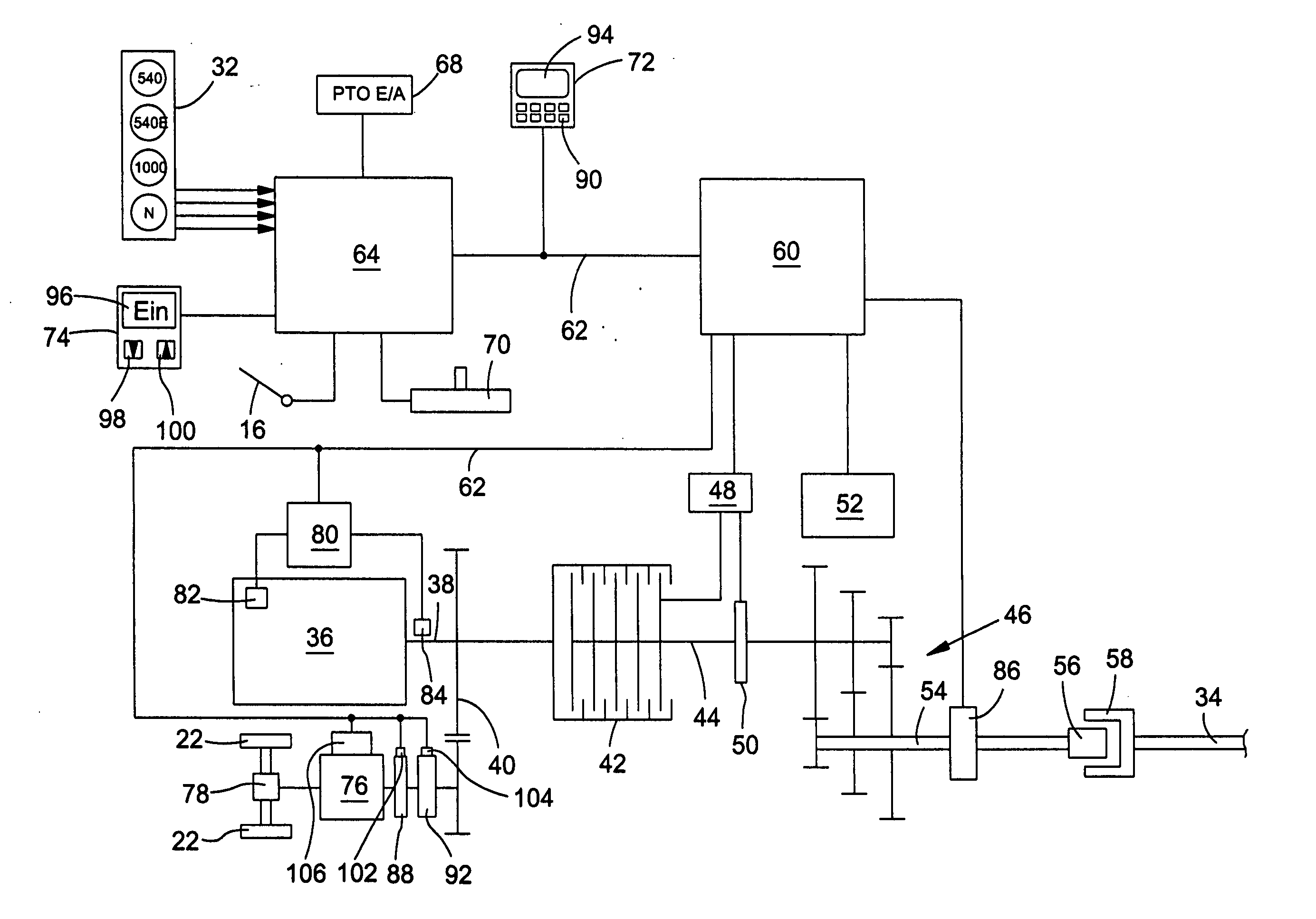
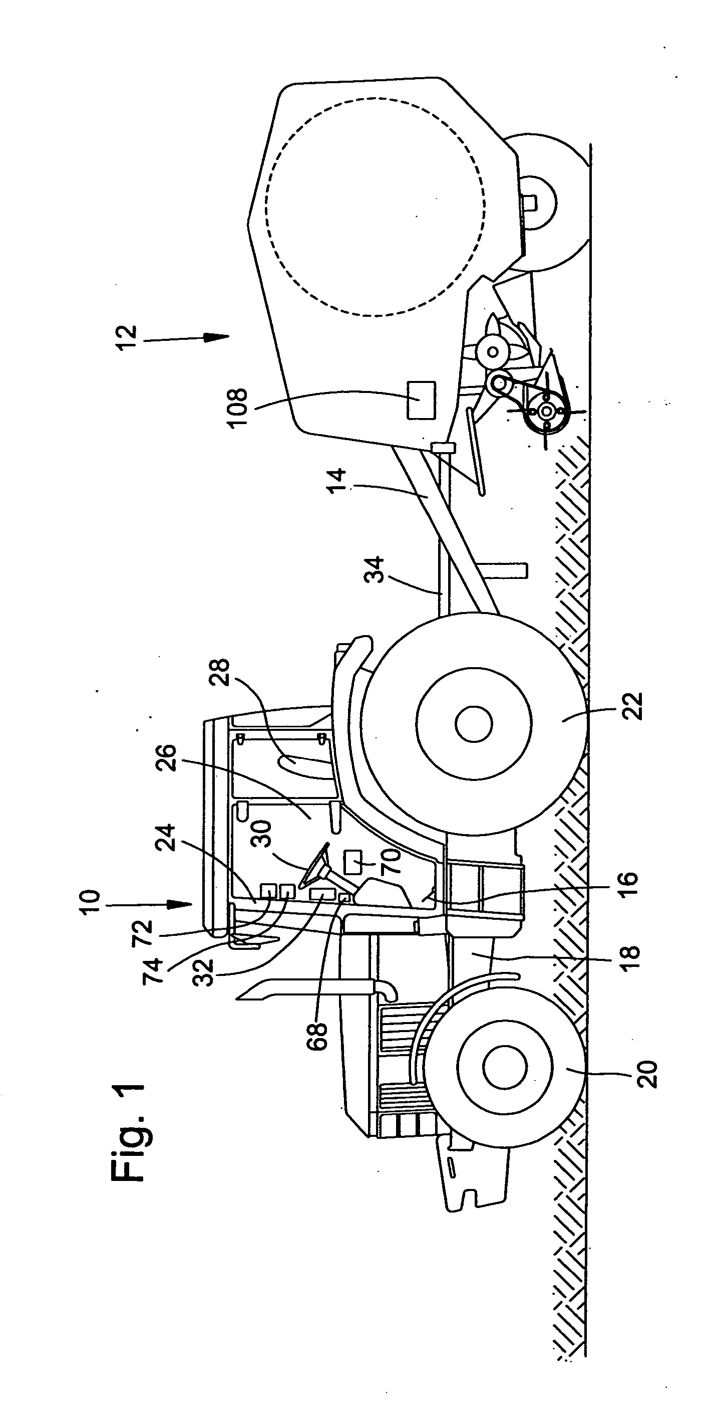
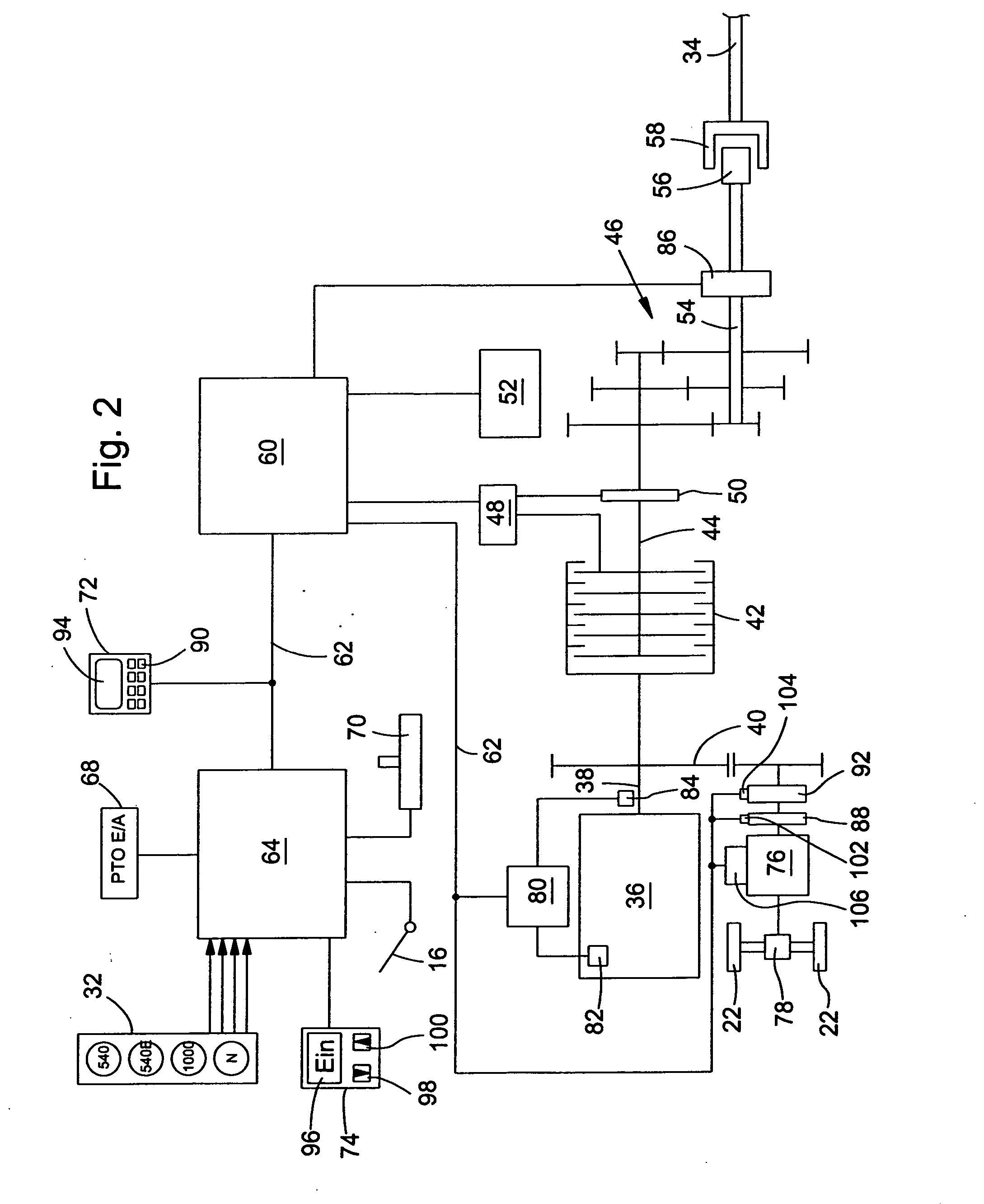
[0019]FIG. 1 shows a lateral view of an agricultural machine 10 in the form of a tractor and an attachment 12 in the form of a round baler coupled to a drawbar clutch (not shown) of the machine 10 by means of a shaft 14. Instead of the round baler, or in addition thereto, any other pulled or attached or suspended attachments, such as field choppers or driven agricultural implements, such as rotary harrows or ordered combinations, can be attached to the machine 10. The machine 10 is constructed on a supporting frame 18, which is supported on steerable front wheels 20 and movable rear wheels 22, and supports a cabin 24 where the operator's workstation 26 is located.

[0020] The operator's workstation 26 includes a seat 28, a steering wheel 30, a gas pedal 16, and another pedal for the brake and clutch (not shown), and input elements arranged in the operator's workstation 26 within reach of the operator for setting the selectable functions of the machine 10. The latter includes a select...


PUM


Abstract

A drive assembly for an agricultural machine. A power take off (PTO) output shaft is connected to a driving motor for driving an attachment. A drive transmission is positioned between and interconnects the driving motor and the support wheels of the agricultural machine. An input device is connected to an electronic control unit. A sensor senses the torque transferred between an attachment and the PTO output shaft, and an actuator is configured to change the transmission ratio of the drive transmission, thereby setting the propulsion speed of the agricultural machine such that the torque transferred between the PTO output shaft and an attachment does not exceed a pre-determined value. The electronic control unit further receives data from the input device and calculates a pre-determined value based on the data received, and thereafter controls the actuator accordingly.

Description

BACKGROUND OF THE INVENTION [0001] 1. Technical Field [0002] The invention relates to a drive assembly of an agricultural machine with a driving engine, which is connected to a power take off (PTO) output shaft for driving an attachment, wherein the torque taken off at the PTO output shaft is limited to a predefined desired value. [0003] 2. Background of the Invention [0004] In the prior art, agricultural tractors are equipped with a driving engine, which in operation drives the wheels to advance the tractor, and a power take-off shaft, which is used to drive attachments, such as agricultural implements or balers. A power take-off gearbox is switched between the engine and the PTO output shaft. Such power take-off gearboxes normally have several transmission stages, which may be selected by an operator, and result in the desired speeds of the PTO shaft. The transmission ratio of a drive transmission inserted into the drive train between the driving engine and the wheels can be charg...

Claims


Application Information

Patent Timeline
Patent Type & Authority Applications(United States)
IPC IPC(8): F16H37/00
CPCA01B71/06A01F15/0841Y10T477/679Y10T477/676A01F15/085
Inventor TARASINSKI, NICOLAIREINARDS, MARCO
Owner DEERE & CO
Why Eureka
Try Eureka