Workpiece motion guide and method

Inactive Publication Date: 2006-08-31
BENCH DOG
View PDF16 Cites 7 Cited by
  • Summary
  • Abstract
  • Description
  • Claims
  • Application Information

AI Technical Summary

Benefits of technology

[0012] A motion guide in accordance with the present invention may also be utilized to provide a fulcrum point when performing an operation on a workpiece. The motion guide may be positioned such that a corner or a curved surface of the motion guide is disposed in a desirable location for use as a fulcrum. A motion guide in accordance present invention may be place in any number of positions. A portion of the workpiece may be seated against the corner of the motion guide. In a presently preferred method the machine operator may use his hand(s) to apply forces to a proximal end of the workpiece causing a distal portion of the workpiece to contact a cutting tool while a middle portion of the workpiece rests against the corner of the motion guide. In this manner, the workpiece may be pivoted against the corner of the motion guide allowing the machine operator to obtain a mechanical advantage and to keep his or her hands a desirable distance away from the cutting tool.
[0013] A motion guide in accordance with the present invention may also be utilized to provide a motion stop when performing an operation on a workpiece. This motion stop allows the machine operator to make repeated operations with equivalent results on different workpieces. For example, FIG. 16 illustrates a router table having a router bit and a fence. A first motion guide and a second motion guide are fixed to the fence. A workpiece may be positioned so that it is seated against the fence. The workpiece may be moved relative to

Problems solved by technology

If the motion guide is mounted too far away from the workpiece, insufficient tension will be applied to the piece.
If the

Method used


Image

  • Workpiece motion guide and method
  • Workpiece motion guide and method
  • Workpiece motion guide and method

Examples


Embodiment Construction

[0034] The following detailed description should be read with reference to the drawings, in which like elements in different drawings are numbered identically. The drawings which are not necessarily to scale, depict selected embodiments and are not intended to limit the scope of the invention. Examples of constructions, materials, dimensions, and manufacturing processes are provided for selected elements. Those skilled in the art will recognize that many of the examples provided have suitable alternatives which may be utilized.

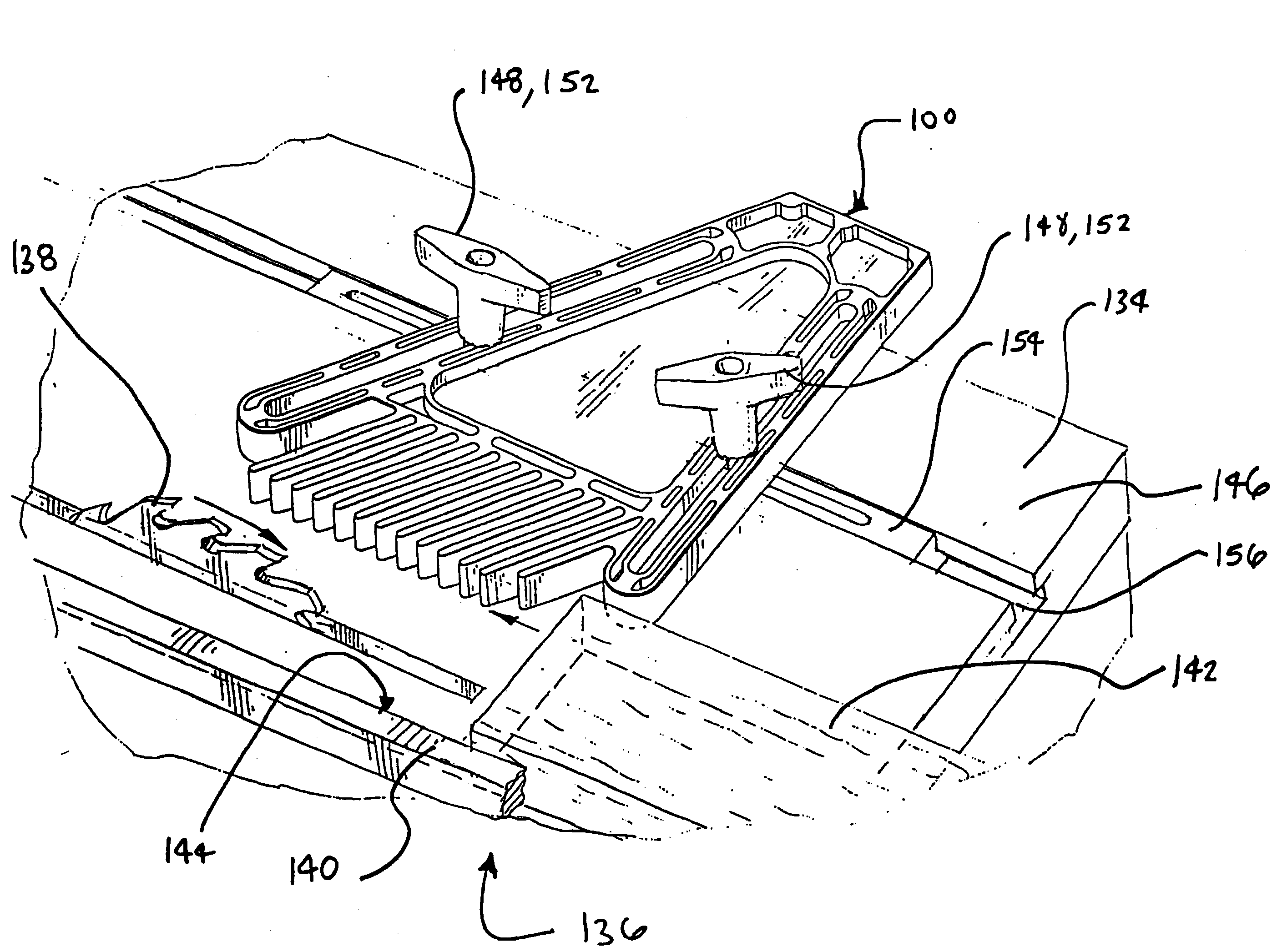
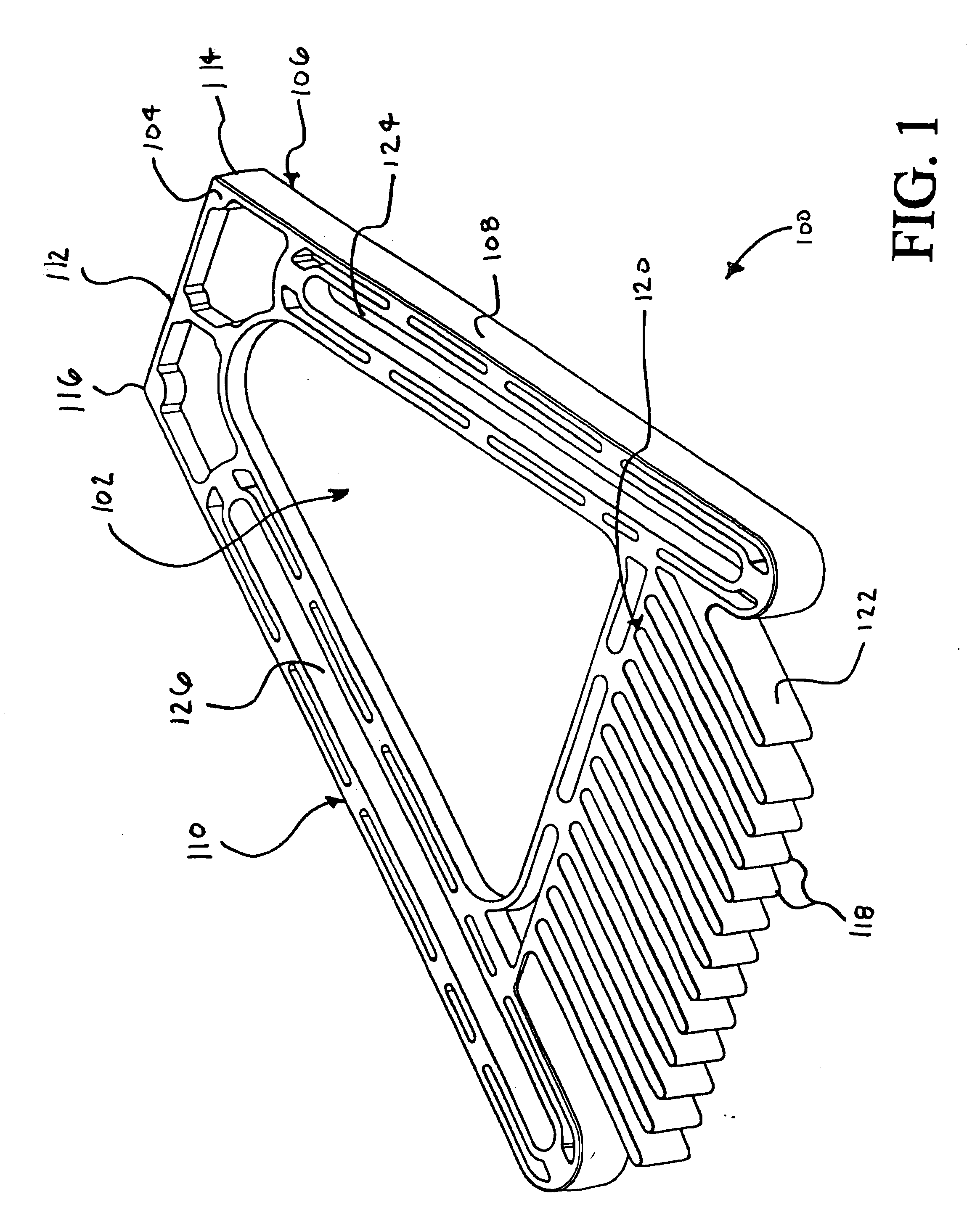
[0035]FIG. 1 is a perspective view of a motion guide 100 in accordance with the present invention. Motion guide 100 includes a body portion 102 defining a top surface 104 and a bottom surface 106. A first guiding surface 108 extends between top surface 104 and bottom surface 106. Motion guide 100 also includes a second guiding surface 110 extending between top surface 104 and bottom surface 106. In the embodiment of FIG. 1, second guiding surface 110 is dispo...


PUM

PropertyMeasurementUnit
Angleaaaaaaaaaa

Abstract

A motion guide for use with a machine having a table is disclosed. A motion guide in accordance with the present invention includes a body portion defining a top surface and a bottom surface, a first guiding surface extending between the top surface and the bottom surface, a second guiding surface extending between the top surface and the bottom surface, the second guiding surface being disposed at an angle relative to the first guiding surface, a plurality of keeper fingers protruding from a keeper surface extending between the top surface and the bottom surface, and disposed between the first guiding surface and the second guiding surface, the keeper fingers being generally parallel to each other, and an alignment member protruding from the keeper surface.

Description

[0001] This application is a continuation of U.S. patent application Ser. No. 10 / 788,865 filed Feb. 27, 2004, which is a continuation application of U.S. patent application Ser. No. 10 / 093,074 filed Mar. 6, 2002, now abandoned, which is a continuation application of U.S. patent application Ser. No. 09 / 496,500 filed Feb. 2, 2000, now abandoned.FIELD OF THE INVENTION [0002] The present invention relates generally to machines and tools for cutting and shaping wood. More particularly, the present invention relates to device which may be utilized to guide the motion of a wooden workpiece past a rotating cutter. BACKGROUND OF THE INVENTION [0003] Many woodworking methods such as routing, joining and cutting involve the step of moving a workpiece past a rotating cutting tool. These operations are typically performed on a woodworking machine having a table. Examples of such machines include routertables, shapers, joiners, jointers, and table saws. Examples of rotating cutting tools include ...

Claims


Application Information

Patent Timeline
IPC IPC(8): B23D1/30B27C5/00B25H1/00B23D3/06B23D5/04B23D9/00
CPCB27B27/00Y10T409/303416B27C5/06
Inventor FONTAINE, NORSTON
Owner BENCH DOG
Why Eureka
Try Eureka