Background of the invention and prior art

a heat exchanger and plate technology, applied in indirect heat exchangers, laminated elements, lighting and heating apparatuses, etc., can solve the problems of high manufacturing cost and space requirements of heat exchanger devices, and achieve low manufacturing cost, compact and simple construction, and efficient heat transfer

Active Publication Date: 2006-08-31
ALFA LAVAL CORP AB
View PDF11 Cites 21 Cited by
  • Summary
  • Abstract
  • Description
  • Claims
  • Application Information

AI Technical Summary

Benefits of technology

[0007] The object of the present invention is to provide a plate package ensuring an efficient heat transfer an...

Problems solved by technology

The disadvantage of such separate liquid separators is that they require space in the heat exchanger dev...

Method used


Image

  • Background of the invention and prior art
  • Background of the invention and prior art
  • Background of the invention and prior art

Examples


Embodiment Construction

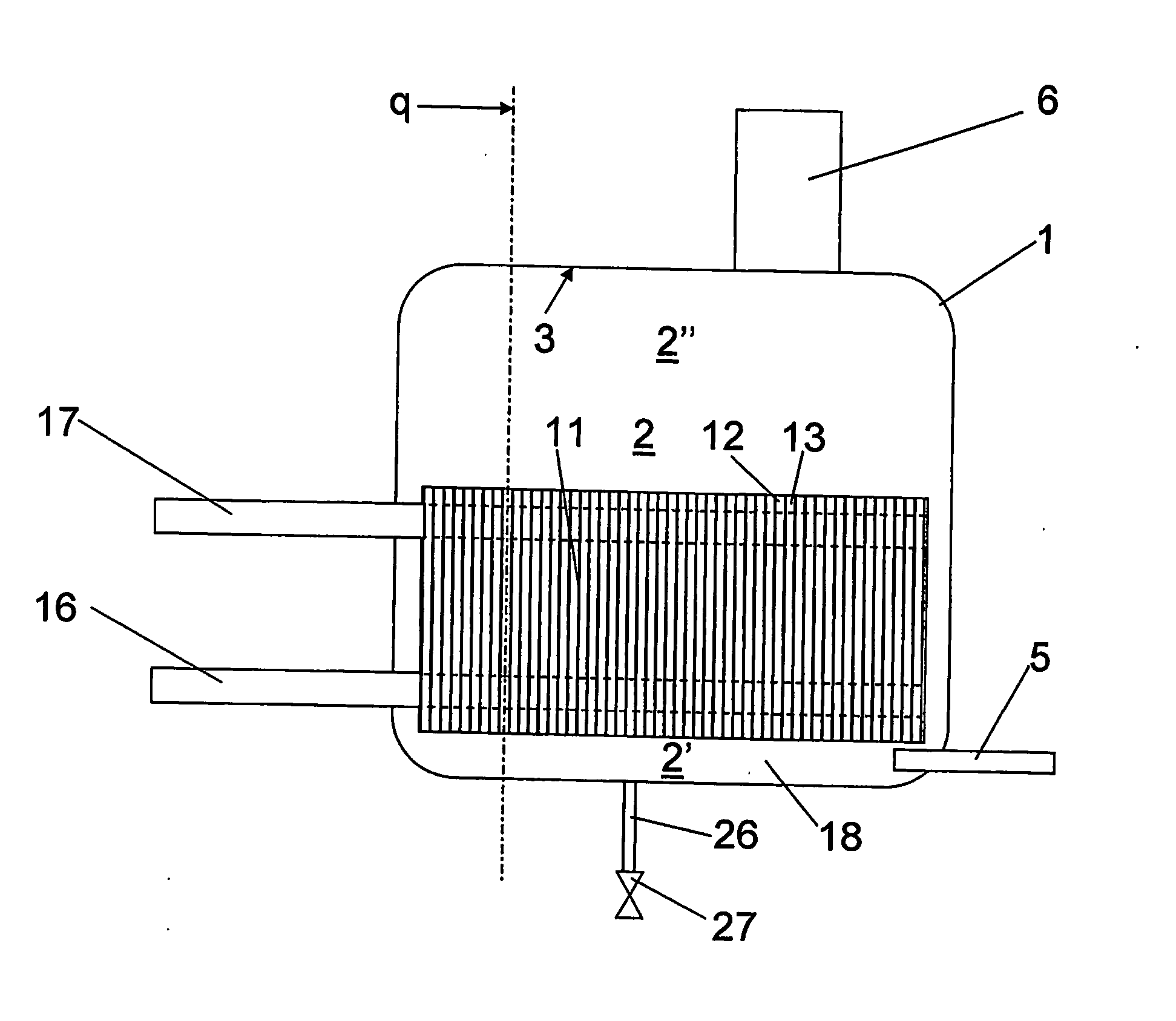
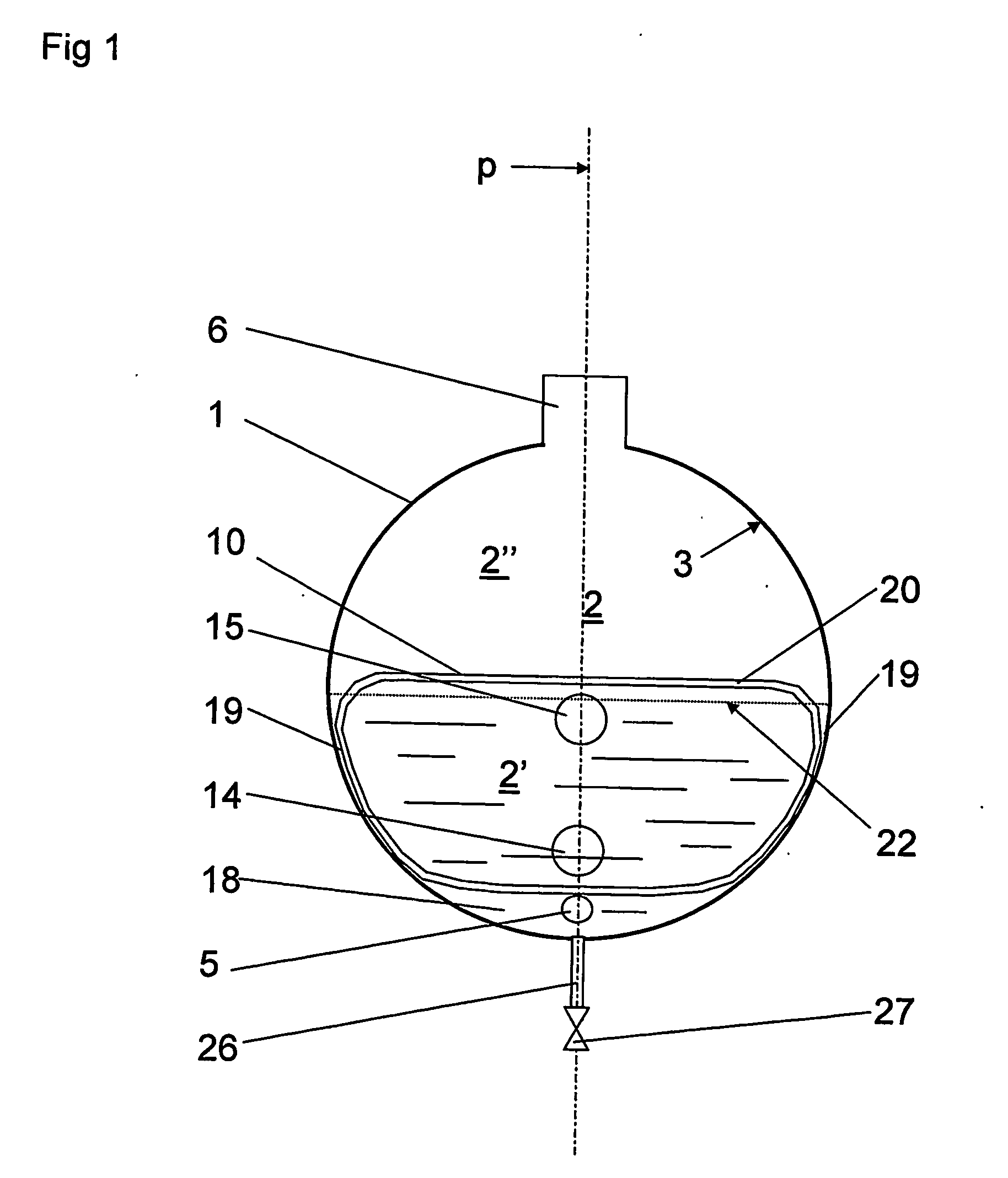
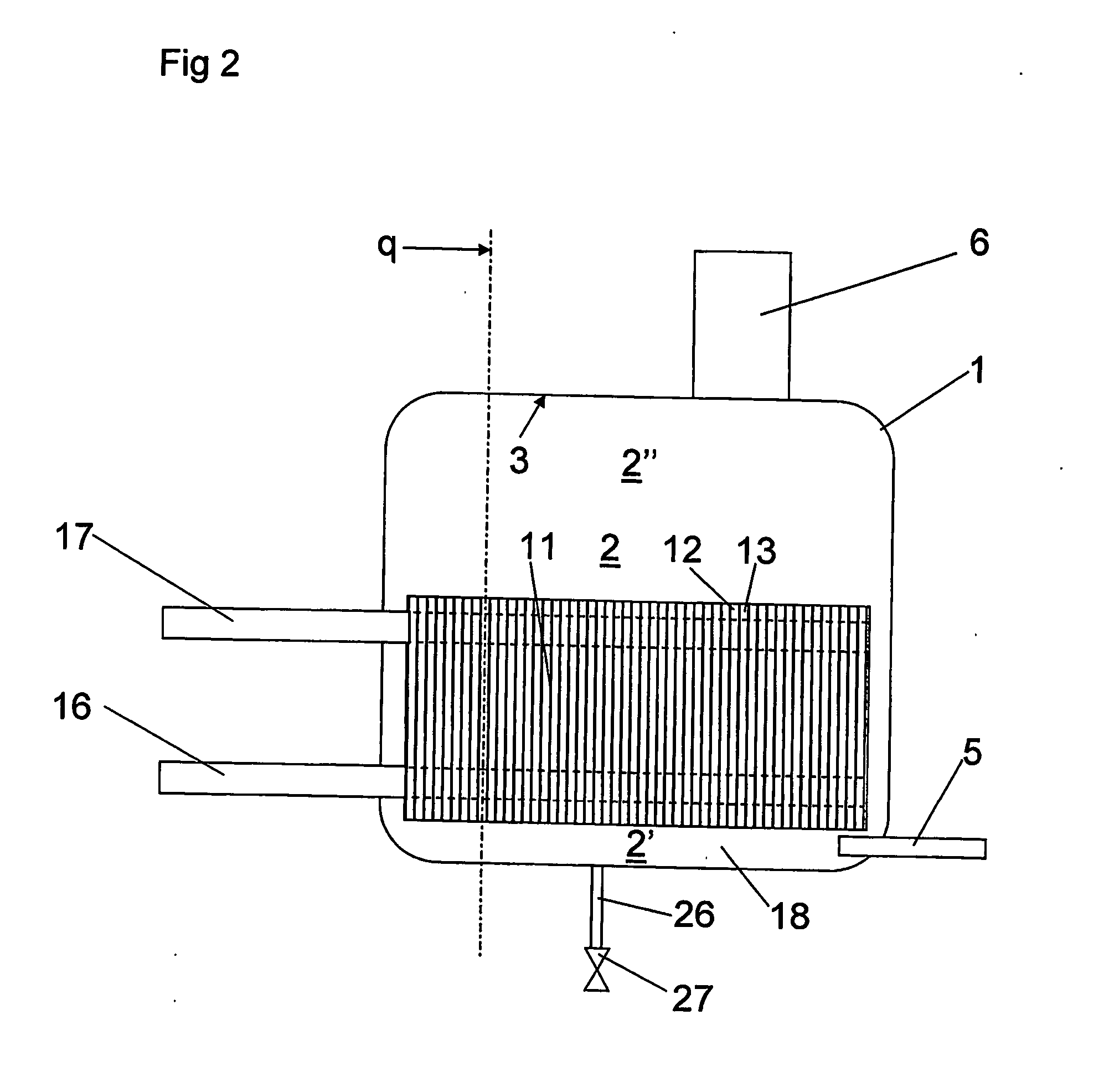
[0024] Referring to FIGS. 1 and 2, a heat exchanger device according to the invention is disclosed. The heat exchanger device includes a tank 1, which forms a substantially closed inner space 2. In the embodiment disclosed the tank 1 has a substantially cylindrical shape with a substantially cylindrical shell wall, see FIG. 1, and two substantially plane end walls. The end walls may also have a semi-spherical shape, for instance. Also other shapes of the tank 1 are possible. The shell wall of the tank 1 forms a substantially cylindrical inner wall surface 3 facing the inner space 2. Through the tank 1 and the inner space 2, a sectional plane p extends. The tank 1 is arranged to be provided in such a way that the sectional plane p is substantially vertical.

[0025] The tank 1 also includes an inlet 5 for the supply of a medium in a liquid state to the inner space 2, and an outlet 6 for the discharge of the medium in a gaseous state from the inner space 2. The inlet 5 includes an inlet...


PUM


Abstract

The invention refers to a plate package for a heat exchanger device including a tank with an inner space and an inner wall surface. A sectional plane (p) extends vertically through the inner space. The tank has an inlet for the supply of a liquid medium and an outlet for discharging the medium in a gaseous state. The inner space defines a lower part space and an upper part space. The plate package (10) with heat exchanger plates (11) is provided in the inner space. Each heat exchanger plate has an extension plane perpendicular to the sectional plane. The heat exchanger plates form first plate interspaces, that are open towards the inner space for recirculation of the medium, and second plate interspaces, which are closed towards the inner space for the recirculation of a fluid for evaporating the medium. Each heat exchanger plate includes a first porthole (14) and a second porthole (15). Furthermore, each heat exchanger plate includes an elongated distribution element (25) which extends into the adjacent second plate interspace and substantially transversally to the sectional plane (p).

Description

THE BACKGROUND OF THE INVENTION AND PRIOR ART [0001] The present invention refers to a plate package for a heat exchanger device including a tank, which forms a substantially closed inner space and which includes an inner wall surface facing the inner space, wherein the tank is arranged to be provided in such a way that a sectional plane, which extends through the plate package and the inner space of the tank, is substantially vertical, wherein the plate package is arranged to be provided in the inner space and includes heat exchanger plates provided adjacent to each other, wherein each heat exchanger plate has a main extension plane and is provided in such a way that the extension plane is substantially perpendicular to said sectional plane, wherein the heat exchanger plates form first plate interspaces, which are substantially open to the inner space and arranged to permit circulation of said medium from the lower part space upwardly to the upper part space, and second plate inter...

Claims


Application Information

Patent Timeline
IPC IPC(8): F28F3/08F28D9/00F28F3/04
CPCF28D9/0006F28D9/0043F28D21/0017F28D2021/0064F28F3/04F28F2250/102
Inventor STENHEDE, CLAESSTROMBLAD, MATSLARSSON, ROLAND
Owner ALFA LAVAL CORP AB
Why Eureka
Try Eureka