Bonded assembly having improved adhesive bond strength

Inactive Publication Date: 2006-08-31
ZAMTEC
View PDF23 Cites 35 Cited by
  • Summary
  • Abstract
  • Description
  • Claims
  • Application Information

AI Technical Summary

Benefits of technology

[0038] Optionally, the first substrate cools during the bonding process. This is usually achieved by heating the first substrate (which may also melt the adhesive), and then allowing it to cool whi

Problems solved by technology

However, when bonding microscale substrates, such as semiconductor integrated circuits (“chips”), it is generally not desirable to abrade a surface of the substrate.
Any defects on the surface of the integrated circuit can result in crack propagation and significantly weaken the device.
Moreover, mechanical grinding can result in d

Method used


Image

  • Bonded assembly having improved adhesive bond strength
  • Bonded assembly having improved adhesive bond strength
  • Bonded assembly having improved adhesive bond strength

Examples


Example

[0106] A specific form of the invention is described below in the context of fabricating a printhead assembly for an inkjet printer. However, it will be appreciated that the invention may be used in connection with bonding any two substrates together and is not in any way limited to the specific embodiment of printhead fabrication.

Inkjet Printer Unit

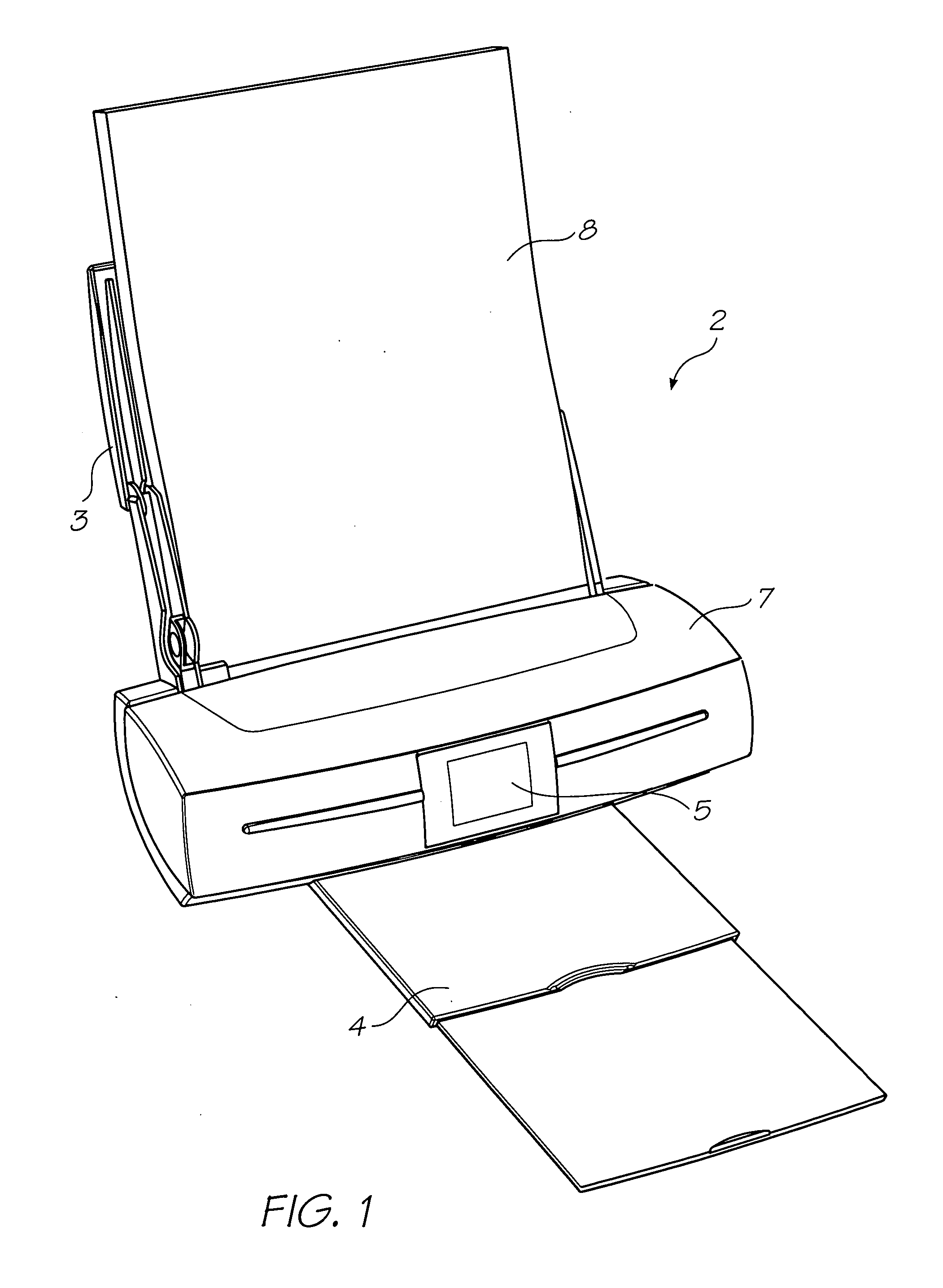
[0107]FIG. 1 shows a printer unit 2 comprising a media supply tray 3, which supports and supplies media 8 to be printed by the print engine (concealed within the printer casing). Printed sheets of media 8 are fed from the print engine to a media output tray 4 for collection. User interface 5 is an LCD touch screen and enables a user to control the operation of the printer unit 2.

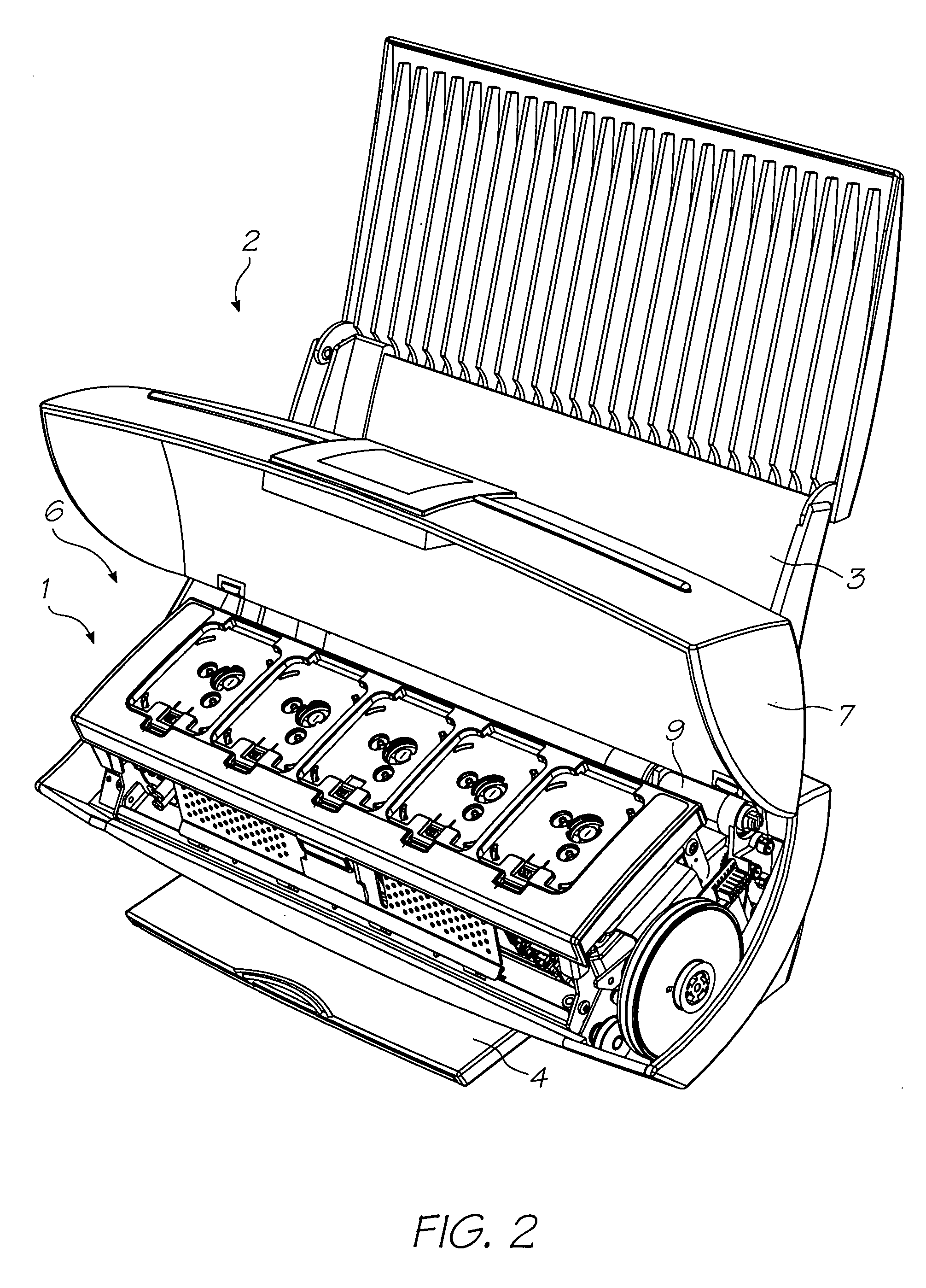
[0108]FIG. 2 shows the lid 7 of the printer unit 2 open to expose the print engine 1 positioned in the internal cavity 6. Picker mechanism 9 engages the media in the input tray 3 (not shown for clarity) and feeds individual streets to the print engine 1. The ...


PUM

PropertyMeasurementUnit
Fractionaaaaaaaaaa
Thicknessaaaaaaaaaa
Thicknessaaaaaaaaaa

Abstract

A bonded assembly is provided. The bonded assembly comprises: (a) a first substrate having a plurality of etched trenches defined in a first bonding surface; and (b) a second substrate having a second bonding surface. The second bonding surface is bonded to the first bonding surface with an adhesive and the adhesive is received, at least partially, in the plurality of etched trenches. Semiconductors chips bonded to a second substrate exemplify the advantages of the invention. The etched trenches allow the adhesive bond to be strengthened whilst avoiding increased surface roughening.

Description

CO-PENDING APPLICATIONS [0001] The following applications have been filed by the Applicant simultaneously with the present application: PBA001USPBA002USPBA004USPBA005US The disclosures of these co-pending applications are incorporated herein by reference. The above applications have been identified by their filing docket number, which will be substituted with the corresponding application number, once assigned. CROSS REFERENCES TO RELATED APPLICATIONS [0002] The following patents or patent applications filed by the applicant or assignee of the present invention are hereby incorporated by cross-reference. 679521510 / 884881PEC01NP09 / 57510910 / 29653509 / 575110680541909 / 607985639833263945736622923674776010 / 18945910 / 94394110 / 94929410 / 72718110 / 72716210 / 72716310 / 72724510 / 72720410 / 72723310 / 72728010 / 72715710 / 72717810 / 72721010 / 72725710 / 72723810 / 72725110 / 72715910 / 72718010 / 72717910 / 72719210 / 72727410 / 72716410 / 72716110 / 72719810 / 72715810 / 75453610 / 75493810 / 72722710 / 72716010 / 93472010 / 85452110 / 8545221...

Claims


Application Information

Patent Timeline
IPC IPC(8): H01L29/82
CPCB41J2/14024B41J2/14427B41J2/155B41J2/1623B41J2/1626B41J2/1648B41J2002/14362B41J2002/14419B41J2002/14435B41J2002/14491B41J2202/20
Inventor SILVERBROOK, KIA
Owner ZAMTEC
Why Eureka
Try Eureka