
Antenna module and electronic device using the same

Inactive Publication Date: 2006-08-31
SAMSUNG ELECTRO MECHANICS CO LTD
View PDF6 Cites 19 Cited by
  • Summary
  • Abstract
  • Description
  • Claims
  • Application Information

AI Technical Summary

Benefits of technology

[0016] The present invention has been made to solve the foregoing problems of the prior art and it is therefore an object of the present invention to provide an antenna module which can minimize occupying space in an electronic device without changing the characteristics of an antenna element, enhancing a degree of freedom of installation structure to increase efficiency in space utilization in the device, thereby accommodating miniaturization and multi-functionality of the electronic device, while securing a uniform radiation pattern in all directions, obtaining a broad bandwidth, and an electronic device having the same.

Problems solved by technology

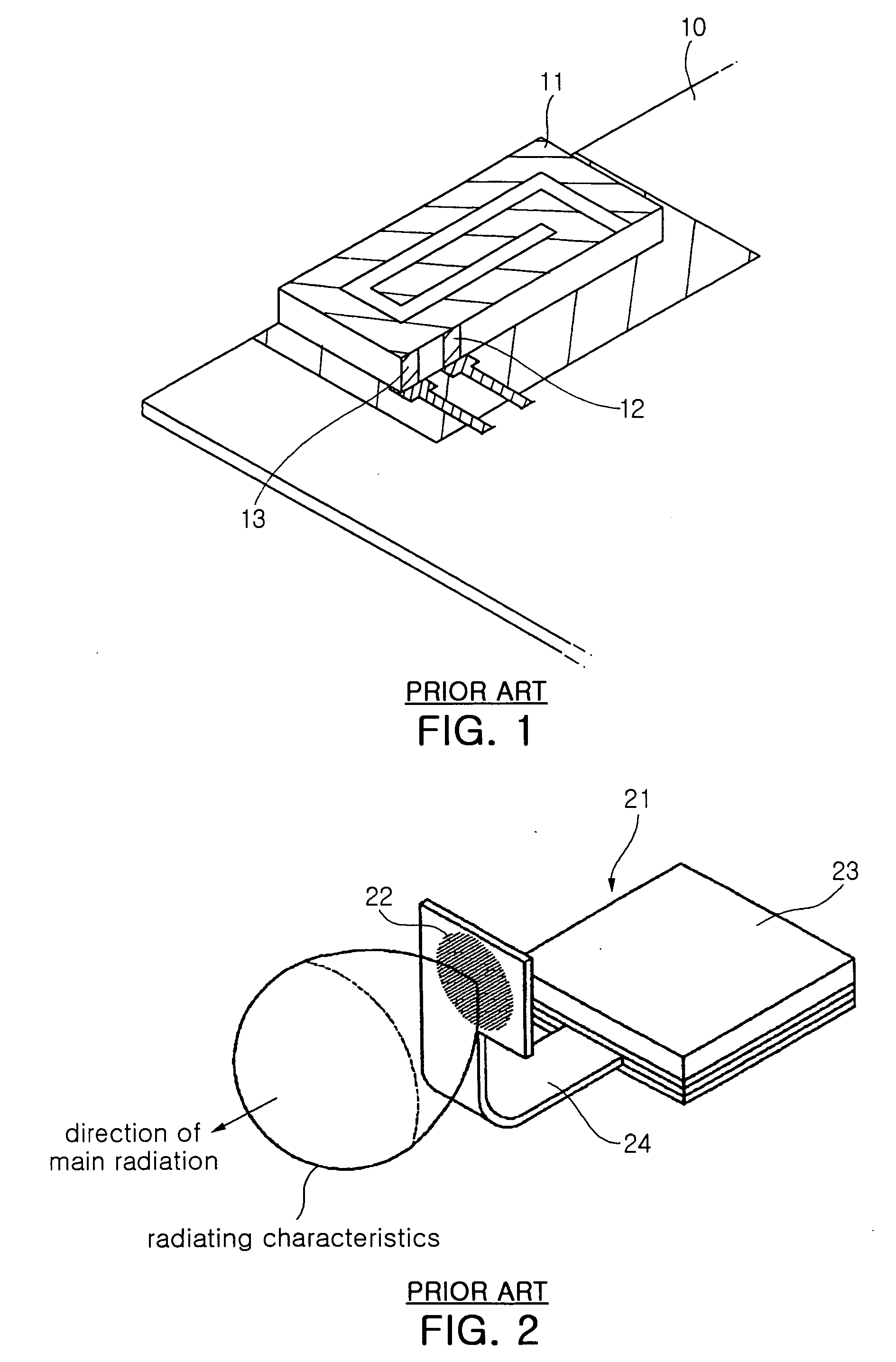
Therefore, the conventional internal antenna takes up a space larger than its size in the wireless electronic device.
However, no matter how small the space is, it is difficult to make a space for the internal antenna in the current miniaturized and multi-functioned wireless electronic devices.

Method used


Image

  • Antenna module and electronic device using the same
  • Antenna module and electronic device using the same
  • Antenna module and electronic device using the same

Examples


Embodiment Construction

[0030] Preferred embodiments of the present invention will now be described in detail with reference to the accompanying drawings. It should be noted that the identical elements are designated by the same reference numerals throughout different drawings. In the following description, well-known functions and constructions are not described in detail since they would obscure the intention in unnecessary detail.

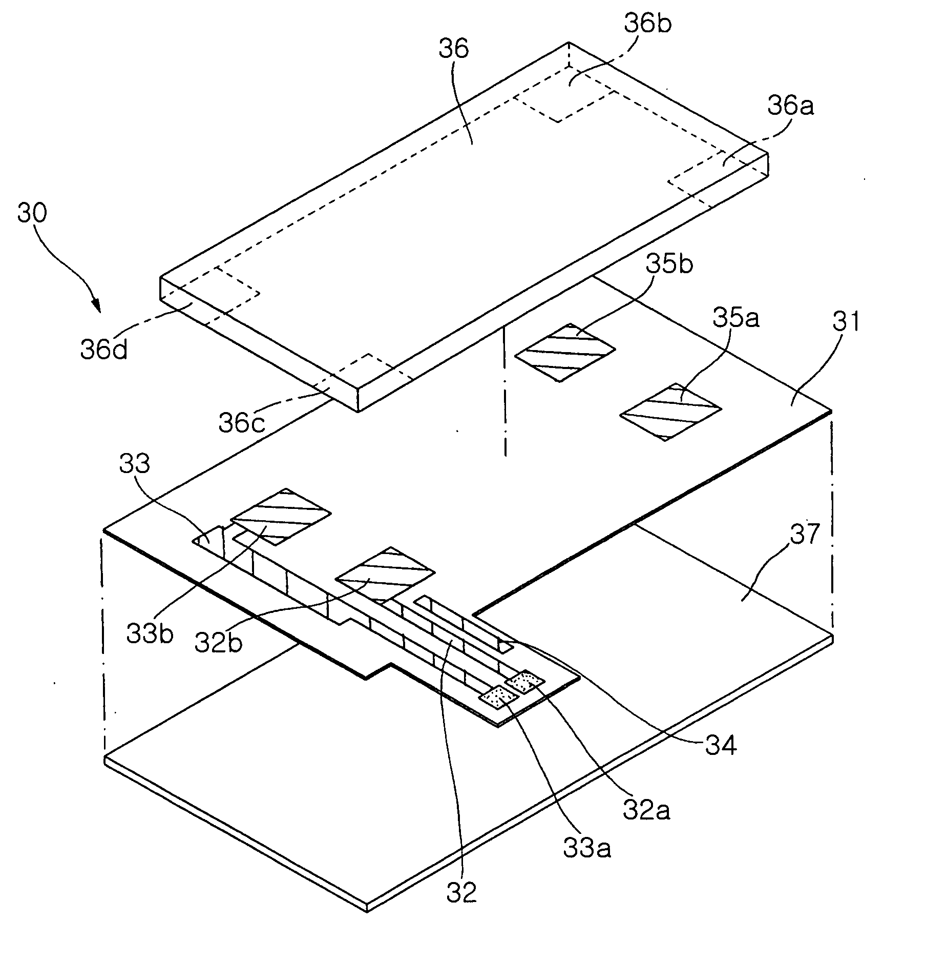
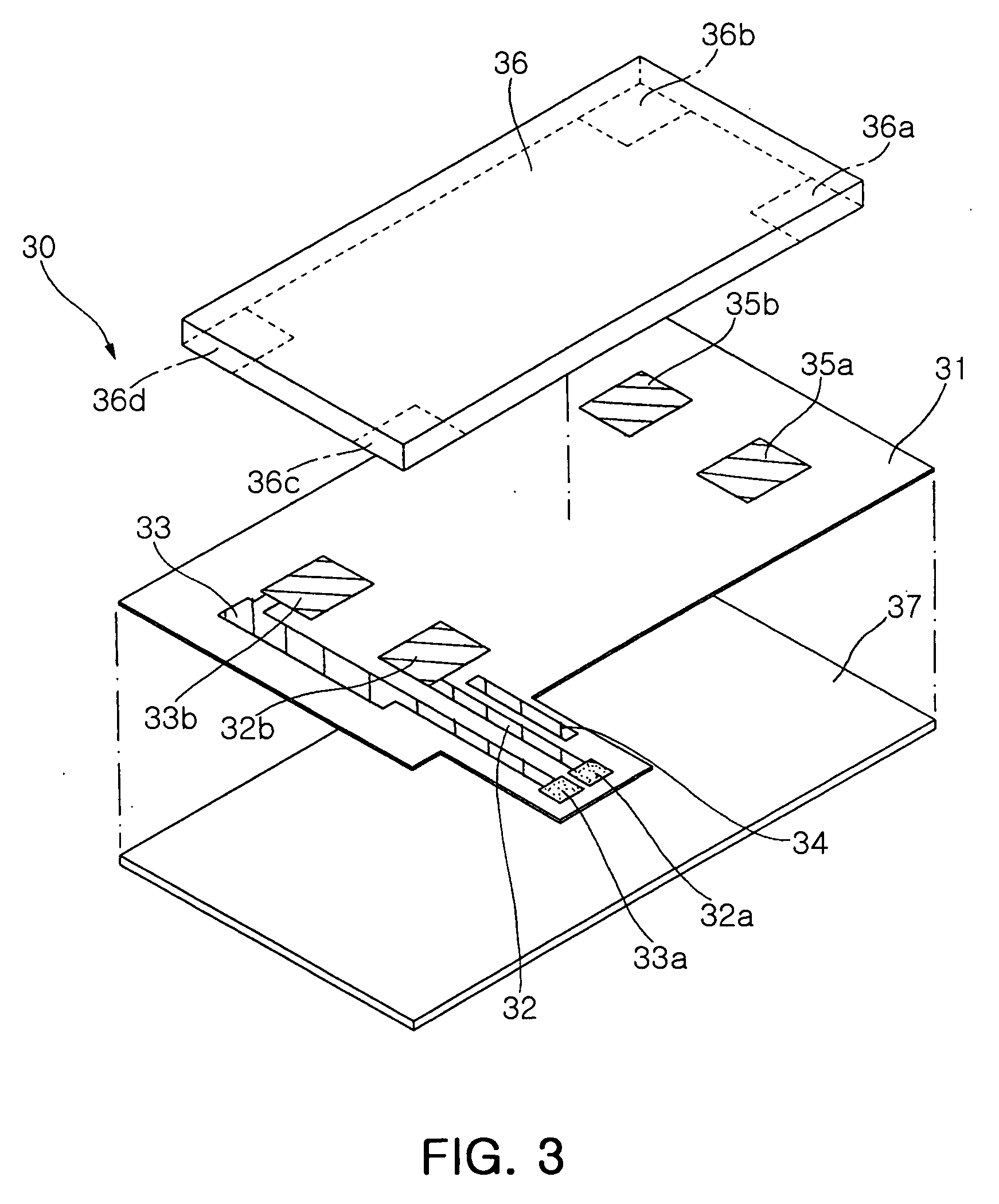
[0031]FIG. 3 is an exploded perspective view illustrating a construction of an antenna module according to the present invention. Referring to FIG. 3, the antenna module 30 according to the present invention includes a substrate 31 made of non-conductive flexible material and an antenna element 36 mounted on the substrate 31.

[0032] On the substrate 31, a ground line 33 for grounding the antenna element 36, a feeder line 32 formed of conductive material at a predetermined position on the substrate 31 to supply current to the antenna element 36, a passive line 34 in parallel wi...


PUM


Abstract

The present invention relates to an antenna module which can minimize the occupying space in an electronic device, enhancing degrees of freedom to increase efficiency in space utilization, thereby accommodating miniaturization and multi-functionality of the electronic device, and an electronic device having the same. The antenna module includes a flexible substrate, an antenna element having a feeder part, a first fixing part, and a radiation part. The antenna module further includes a feeder line connected to the feeder part having a feeder pad, a first fixing pad connected to the first fixing part, and a pad coupling element. In the invention, signals are processed via interaction between the resonance of the current running through the feeder line to the radiation part and the resonance of the current coming into the pad coupling element.

Description

CLAIM OF PRIORITY [0001] This application claims the benefit of Korean Patent Application No. 2005-016103 filed on Feb. 25, 2005, in the Korean Intellectual Property Office, the disclosure of which is incorporated herein by reference. BACKGROUND OF THE INVENTION [0002] 1. Field of the Invention [0003] The present invention relates to an antenna module provided in an electronic device with a wireless communication function. More particularly, the present invention relates to an antenna module which can minimize the occupying space in an electronic device and enhances a degree of freedom of the installation structure of the antenna module, increasing efficiency in space utilization in the electronic device, thereby accommodating miniaturization and multi-functionality of the electronic device, and an electronic device having the same. [0004] 2. Description of the Related Art [0005] The recent advancement in the semiconductor and telecommunication technology has led to extensive use of...

Claims


Application Information

Patent Timeline
IPC IPC(8): H01Q1/38H01QH01Q1/24H01Q9/04
CPCH01Q1/242H01Q1/243H01Q1/38H01Q9/0407H01Q1/12H01Q1/24
Inventor PARK, II HWANKIM, CHUL HODO, GI TAELEE, DUK WOOSEO, JEONG SIKKIM, TAE SUNGOH, SAE WONKIM, HYUN HAK
Owner SAMSUNG ELECTRO MECHANICS CO LTD
Learn More