
Optical unit, method of manufacturing the same, backlight assembly having the same and display device having the same

a technology of optical unit and backlight assembly, which is applied in the direction of instruments, stoves or ranges, combustion types, etc., can solve the problems of light sources decreasing, conventional optical members not effectively overcome the bright line on the display panel, etc., and achieve the effect of enhancing the uniformity of luminance and reducing the applied pressure of mixtur

Inactive Publication Date: 2006-08-31
SAMSUNG ELECTRONICS CO LTD
View PDF6 Cites 8 Cited by
  • Summary
  • Abstract
  • Description
  • Claims
  • Application Information

AI Technical Summary

Benefits of technology

[0009] The present invention overcomes the aforementioned problems and thus the present invention provides an optical unit capable of enhancing light-diffusing characteristics.
[0016] In still another aspect of the present invention, a method of manufacturing an optical unit for a display device comprises mixing polymer with particles, each particle of which has a length of about 1 nm to about 100 nm with respect to at least one direction, pressurizing a foaming agent at a pressure greater than an atmospheric pressure to dissolve the foaming agent in a mixture of the polymer and the particles and reducing a applied pressure of the mixture in which the foaming agent is dissolved to generate bubbles in the mixture.
[0017] According to the above, the optical unit diffuses light that is incident thereupon through the diffusion member to emit light having an enhanced uniformity of luminance.

Problems solved by technology

However, since a conventional optical member does not diffuse the light sufficiently, the conventional optical member does not effectively overcome the bright line on the display panel when the distance between the display panel and the light sources decreases.

Method used


Image

  • Optical unit, method of manufacturing the same, backlight assembly having the same and display device having the same
  • Optical unit, method of manufacturing the same, backlight assembly having the same and display device having the same
  • Optical unit, method of manufacturing the same, backlight assembly having the same and display device having the same

Examples


Embodiment Construction

[0028] The present invention now will be described more fully hereinafter with reference to the accompanying drawings, in which embodiments of the invention are shown. This invention may, however, be embodied in many different forms and should not be construed as being limited to the embodiments set forth herein; rather, these embodiments are provided so that this disclosure will be thorough and complete, and will fully convey the scope of the invention to those skilled in the art. Like reference numerals refer to similar or identical elements throughout.

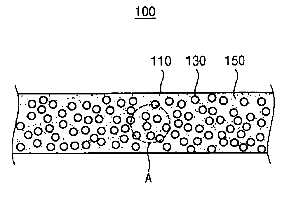
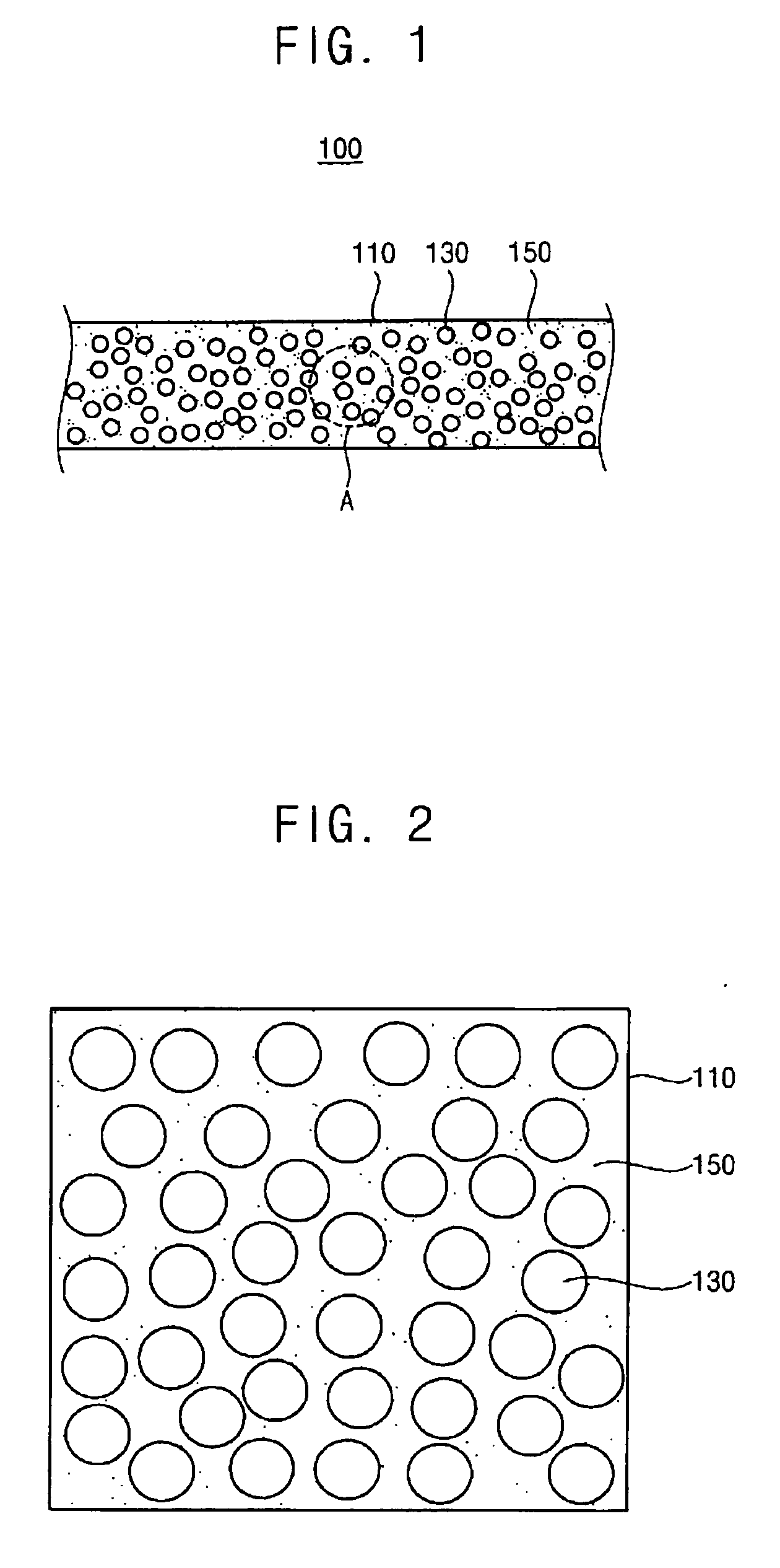
[0029]FIG. 1 is an exemplary cross-sectional view illustrating an optical unit according to the present invention.

[0030] Referring to FIG. 1, an optical unit 100 according to an exemplary embodiment of the present invention includes a body 110, a diffusion member 130 and a control member 150.

[0031] The body 110, for example, is transparent and has a plate-like shape. The body 110 includes polymer resin having good characteristics...


PUM


Abstract

An optical unit includes a body, diffusion members and control members. The diffusion members are disposed in the body to diffuse incident light. The control members are disposed in the body to produce diffusion members having substantially uniform sizes. Thus, the optical unit has an enhanced light-diffusing characteristic, thereby improving the uniformity of luminance of light emitted from the optical unit.

Description

[0001] This application claims priority to Korean Patent Application No. 2005-9505 filed on Feb. 2, 2005, the contents of which are herein incorporated by reference in its entirety. BACKGROUND OF THE INVENTION [0002] 1. Field of the Invention [0003] The present invention relates to an optical unit, a method of manufacturing the optical unit, a backlight assembly having the optical unit and a liquid crystal display device comprising the same. More particularly, the present invention relates to an optical unit capable of enhancing light-diffusing characteristics, a method of manufacturing the optical unit, a backlight assembly comprising the optical unit and a liquid crystal display device comprising the same. [0004] 2. Description of the Related Art [0005] Generally, liquid crystal has electrical characteristics that permit it's molecules to be rearranged by electric fields. This molecular rearrangement also facilitates changes in the optical characteristics of the liquid crystal, su...

Claims


Application Information

Patent Timeline
Patent Type & Authority Applications(United States)
IPC IPC(8): G02B23/00
CPCG02B5/0242G02B5/0268G02B5/0278F23D14/70F24C3/08F24C3/12
Inventor KIM, GEUN-HYUNGPARK, JONG-DAEKIM, TAE-SEOK
Owner SAMSUNG ELECTRONICS CO LTD
Learn More