[0010]This object is achieved by an apparatus according to the invention for observing the optical appearance of the surface of a sample of semitransparent material, in particular a human
skin, which comprises a
light source for illuminating at least a region of interest of the surface of the sample from a predetermined direction, a camera for observing a response to the illumination of the region of interest and an optical focus device for determining if the camera is in focus with at least a part of the surface of the region of interest. In this way it is safeguarded that the camera for observing the optical appearance of the surface of the sample is in focus with at least a part of the surface of the sample. The optical focus device provides that the surface of the sample is optimally focused with respect to the camera even in the case that a deformable surface, such as the human
skin, is deformed by a mechanical contact of a part of the apparatus with the surface of the sample. Hence, the influence of the deformation of the surface of the sample on the quality of the observance of the optical appearance of the sample is minimized, because the optical focus device safeguards that at least a part of the surface of the sample is in focus with the camera. The invention therefore minimizes the occurrence of an observation in which the surface of the sample is not in focus with the camera resulting in a low quality observance and an out-of-focus camera setting.
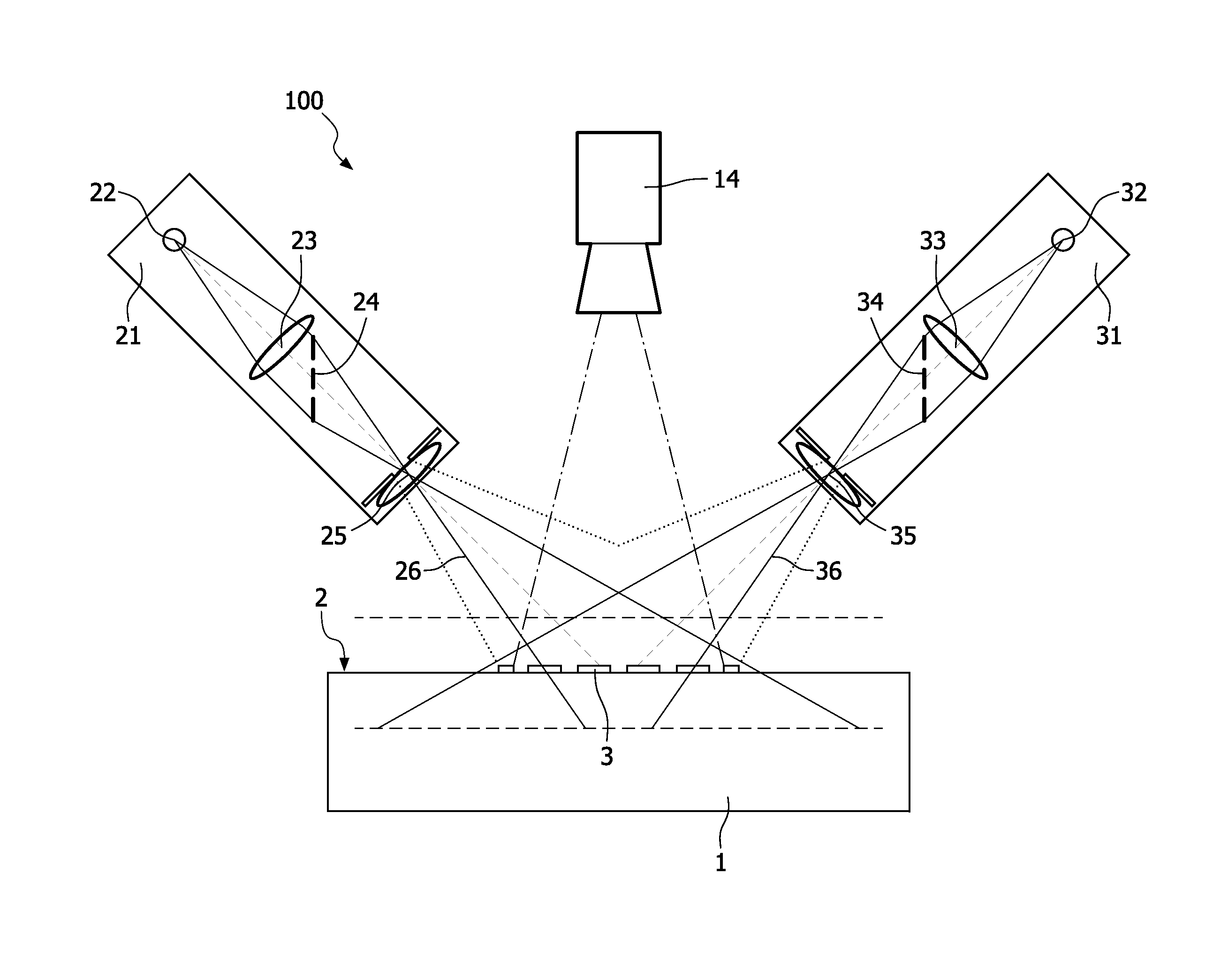
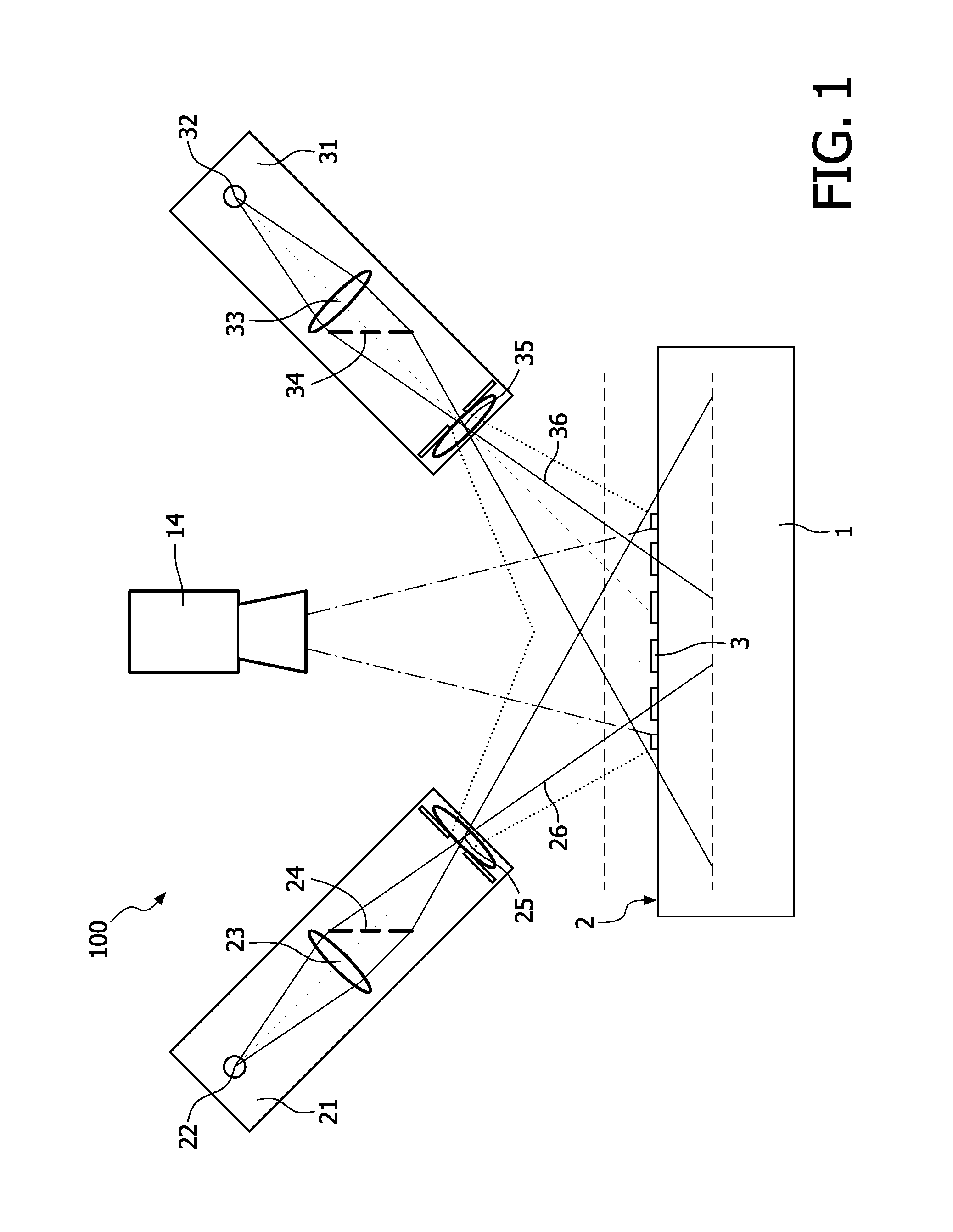
[0011]In an embodiment of the apparatus according to the invention, the optical focus device comprises a focus
light beam which projects a focus image on the surface of the region of interest. The focus
light beam advantageously provides for an image on the surface of the sample which is used to determine if the camera is in focus with the surface of the sample. For example, the focus light beam is projected on the surface of the sample as a point spot. In another example, a
collimated light beam generates a
grid pattern which is projected on the surface of the region of interest, such as a
laser combined with a
holographic grating which projects the
grid pattern on the surface of the sample. Preferably the focus light beam comprises
blue light. This has the
advantage that the
signal to
noise ratio in the observing camera is high, because
blue light has a
high contrast with
skin color. This minimizes the influence of the focus light beam on the image, because
blue light does not penetrate the sample too deep to blur the image captured by the camera.
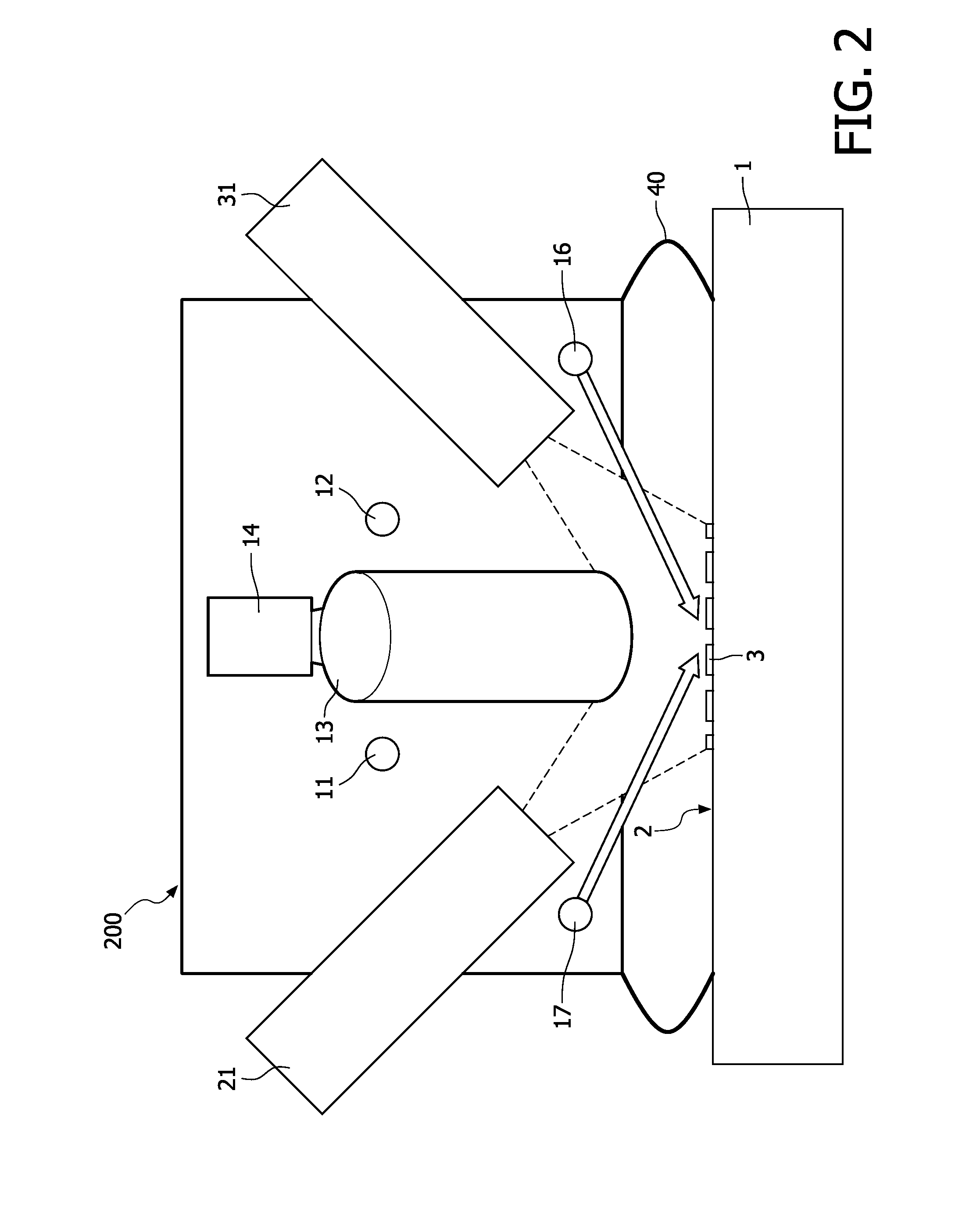
[0015]In an embodiment of the apparatus according to the invention, the apparatus further comprises a deformable contact ring for contacting the surface of the sample on a specific distance from the region of interest and for protecting the surface of the sample from environmental light. The deformable contact ring, such as a
bellows or a soft foam part, provides for a reduction of the pressure applied to the surface of the sample, because it is deformable and flexible and hence will apply less pressure than a
solid contact surface. In this way deformation of a deformable surface is reduced and, in the case of human skin, the discolorization caused by the applied pressure is also reduced. The deformable contact ring further shuts off any unwanted light from the environment which advantageously contributes to the quality of the observance of the surface of the sample.
[0016]In an embodiment of the apparatus according to the invention, the deformable contact ring comprises means for indicating that the deformable contact ring has been used. This advantageously prevents that the deformable contact ring, that contacts the surface of the sample, such as for example the human skin, is used more than once thereby reducing the risk of cross-
contamination between different samples. In another embodiment the means for indicating that the deformable contact ring has been used comprises a visual indicator for contaminants. This visual indicator advantageously provides for a warning of a contaminated deformable contact ring. By replacing the deformable contact ring when it is contaminated, as is indicated by the visual indicator according to the invention, any cross-
contamination between different samples is prevented.
[0021]In a preferred embodiment of the method according to the invention, the method further comprises the step of contacting the surface of the sample on a specific distance from the region of interest with a deformable contact ring before the step of determining the focus, thereby protecting the surface of the sample from environmental light. The deformable contact ring, such as a
bellows or a soft foam part, provides for a reduction of the pressure applied to the surface of the sample, because it is deformable and flexible and hence will apply less pressure than a
solid contact surface. In this way deformation of a deformable surface is reduced and, in the case of human skin, the discolorization caused by the applied pressure is also reduced. The deformable contact ring further shuts off any unwanted light from the environment which advantageously contributes to the quality of the observance of the surface of the sample.


