Pumps for filtration systems

a technology of filtration system and pump, which is applied in the direction of feeding/discharge of settling tank, machine/engine, printing, etc., can solve the problems of large system, unpractical, lack of efficient valve system, etc., and achieves the effect of reducing the applied pressure, simplifying the valve mechanism, and minimizing the concentration of polarization in the ro membran

Inactive Publication Date: 2007-07-17
AQUA RES PTY LTD
View PDF91 Cites 13 Cited by
  • Summary
  • Abstract
  • Description
  • Claims
  • Application Information

AI Technical Summary

Benefits of technology

[0027]A primary advantage of the present invention is a pressure recovery feature in the pump that utilizes a simplified valve mechanism for retentate discharge.
[0028]Another advantage of the apparatus is a pulsing mechanism in the pump that minimizes polarization concentration in the RO membrane thereby significantly reducing the applied pressure and improving the permeate flux produced for a given amount of power applied to the pump.
[0029]Other objects, advantages and novel features, and further scope of applicability of the present invention will be set forth in part in the detailed description to follow, taken in conjunction with the accompanying drawings, and in part will become apparent to those skilled in the art upon examination of the following, or may be learned by practice of the invention. The objects and advantages of the invention may be realized and attained by means of the instrumentalities and combinations particularly pointed out in the appended claims.

Problems solved by technology

High levels of total dissolved solids (TDS) in water, such as dissolved salts in seawater, make the water unfit for drinking because of the ion imbalance in the human system.
There are many settings in which these large systems are not practical.
This feature does not apply to fluids such as water and lacks an efficient valve system for retentate discharge and for isolating the RO element in the event that TDS removal is not required.
The mechanism does not incorporate an efficient pressure relief and retentate discharge mechanism integral to the piston and rod assembly.

Method used


Image

  • Pumps for filtration systems
  • Pumps for filtration systems
  • Pumps for filtration systems

Examples


example 1

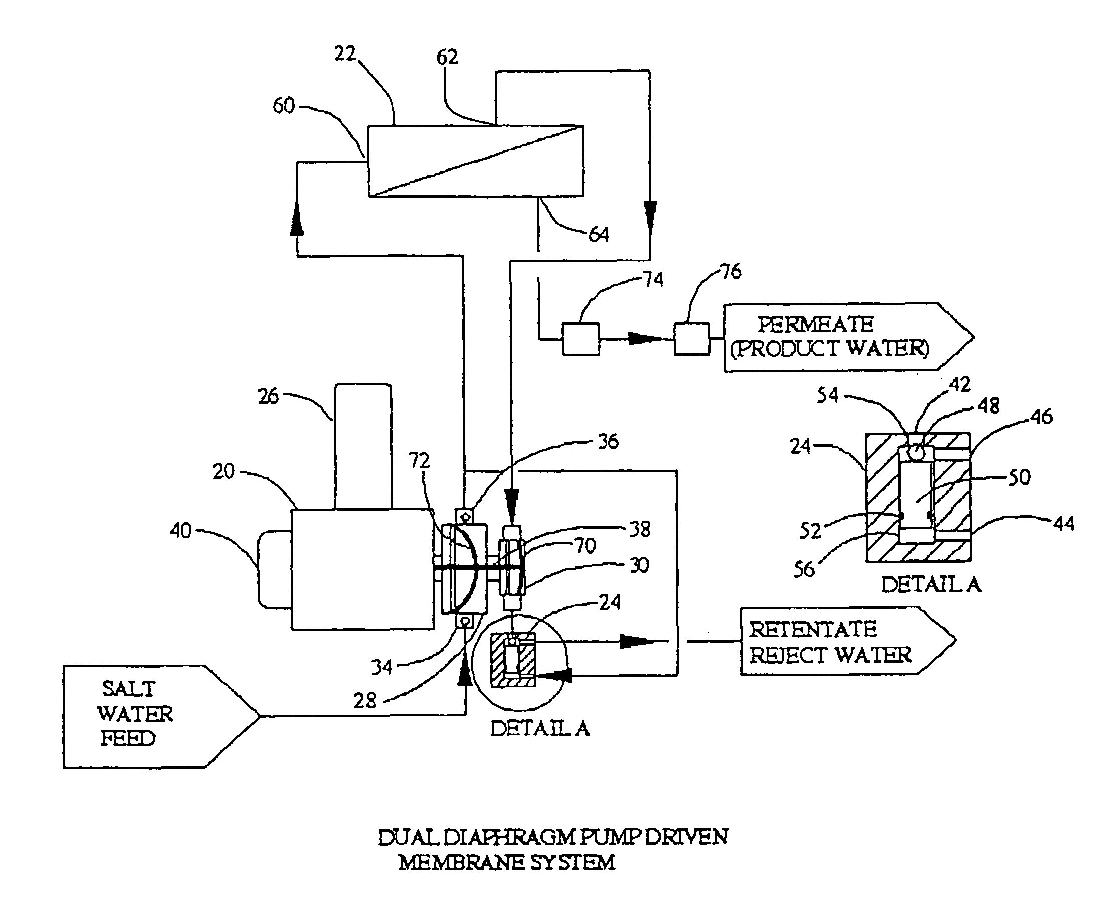
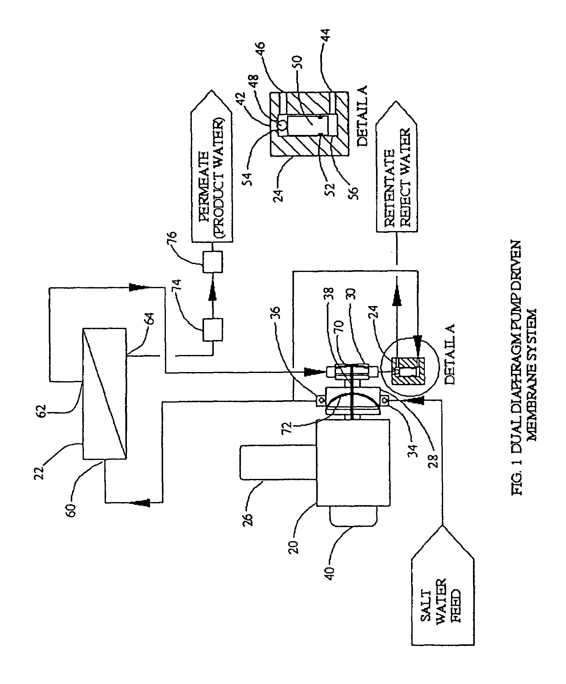
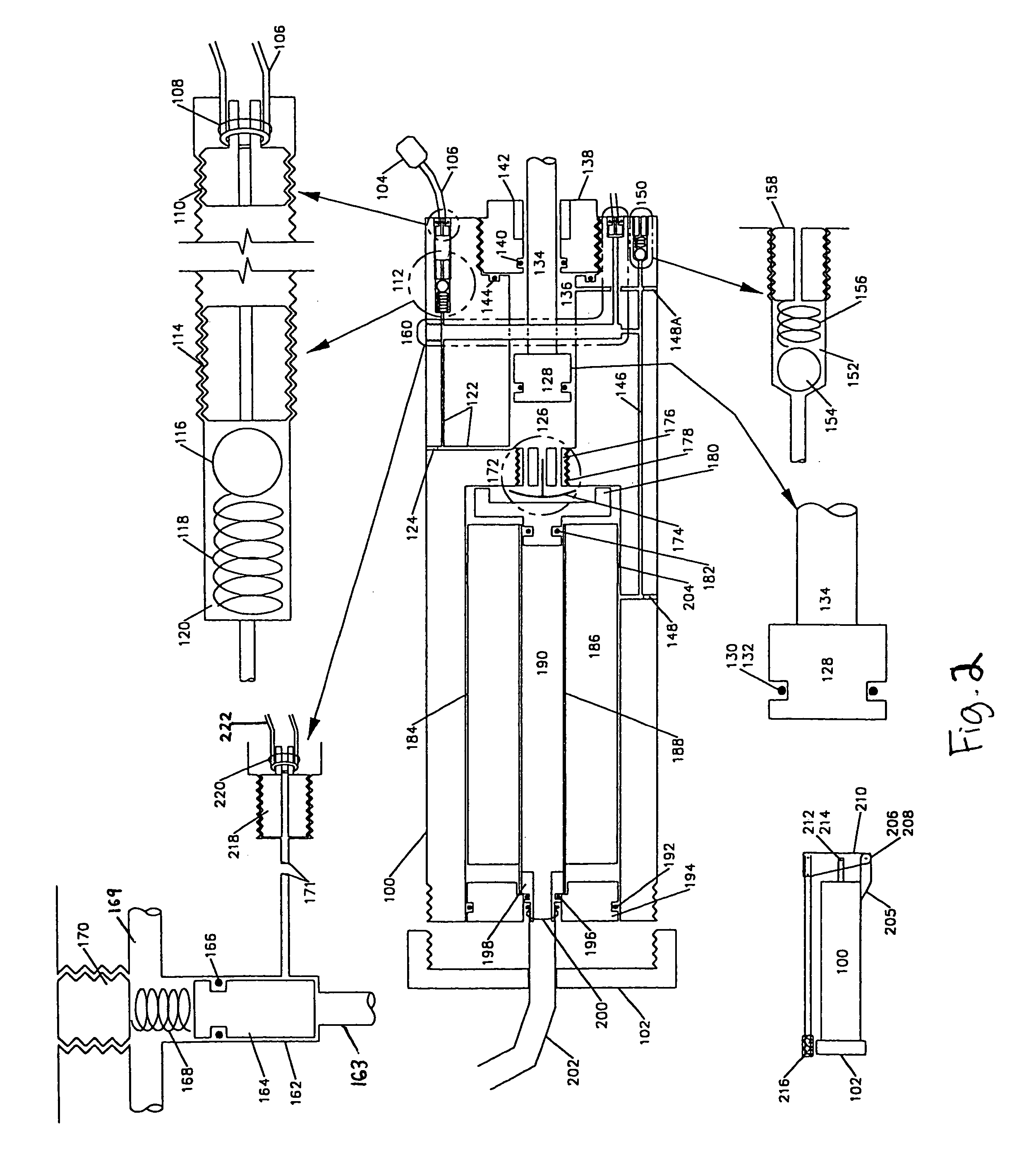
[0049]The present invention was developed under a contract funded the U.S. Department of Defense's Defense Advanced Research Projects Agency (“DARPA”) to produce a small portable system that will allow individual soldiers to treat any water anywhere to drinking water quality. The research did not focus on membrane chemistry, but rather construction and hydraulic flow characteristics of spiral-wrapped RO element designs. Concurrent with design of the RO elements, a hand pump device was developed that utilizes various features including a simple differential pressure activated valve to produce pressure recovery in the pump to significantly reduce the applied force required to operate the pump.

[0050]Advantages of the invention, as demonstrated by the research, include as follows:

[0051]Enhanced Recovery. Recovery is defined as the amount of permeate water (clean product water) divided by the volume of feed water that enters an RO element. Typically, RO elements operating on seawater uti...


PUM

PropertyMeasurementUnit
diameteraaaaaaaaaa
diameteraaaaaaaaaa
lengthaaaaaaaaaa

Abstract

Improvements in product water throughput from a reverse osmosis (RO) membrane filter achieved by thinner feed spacers in the RO element, enhanced recovery (ratio of permeate to feed), pressure recovery of the retentate fluid pressure opposing the feed water pressure, and fluid pulsing of the RO element feed stream. The system of the invention preferably comprises a dual head reciprocating pump, an RO element, and a differential pressure activated (“DPA”) valve. The DPA valve, in combination with connecting the two pump heads to reduce required pump pressures, generates energy recovery. The frequency and amplitude of the reciprocating pump create a pulse wave in the RO element that improves permeate quality and throughput. A control system preferably monitors system parameters to optimize the reciprocating pump speed and amplitude in order to obtain maximum throughput and permeate quality from any given RO element configuration. Also a highly compact, portable RO system comprising a piston and a DPA valve. The piston separates the feed chamber from the retentate chamber. The pressure difference between the two chambers determines the pressure recovery of the system. The DPA valve opens and closes hydraulically to automatically control the retentate discharge as the system is pumped.

Description

CROSS-REFERENCE TO RELATED APPLICATIONS[0001]This application claims priority to U.S. Provisional Patent Application Ser. No. 60 / 446,830, entitled “In-Line Reverse Osmosis Pump”, filed on Feb. 11, 2003, and is a continuation-in-part of PCT Application Serial No. PCT / US02 / 22618, entitled “Dual Head Driven Membrane System”, filed on Jul. 16, 2002, which claims priority to U.S. Provisional Patent Application Ser. No. 60 / 305,912, entitled “In-Line Reverse Osmosis Pump”, filed on Jul. 16, 2001.[0002]This application is also a continuation-in-part of U.S. patent application Ser. No. 09 / 907,092, entitled “Portable Water Disinfection System”, filed on Jul. 16, 2001, now U.S. Pat. No. 6,736,966, which is a continuation-in-part of, and claims priority to, U.S. patent application Ser. No. 09 / 318,468, entitled “Portable Water Disinfection System”, filed on May 25, 1999, now issued as U.S. Pat. No. 6,261,464; and which is a continuation-in-part of U.S. patent application Ser. No. 09 / 514,431, ent...

Claims


Application Information

Patent Timeline
Patent Type & Authority Patents(United States)
IPC IPC(8): B01D63/00B01D61/06B01D63/10B01D61/00B01D61/04B01D61/08B01D61/10B01D61/12B01D65/08B01D67/00B01D69/00B01D69/02B01D69/14B29C41/20B29C67/00B41J2/01B41J3/407C02F1/00C02F1/44C02F1/461C02F1/467C02F9/00F04B9/107F04B9/14F04B43/02F04B43/04F04B43/073
CPCB01D61/04B01D61/147B01D61/08B01D61/10B01D61/12B01D63/10B01D65/08B01D67/0088B01D69/00B01D69/02B01D69/141B29C41/20B41J2/01B41J3/407C02F1/46104C02F1/4674C02F9/005F04B9/107F04B9/14F04B43/02F04B43/04F04B43/073B01D61/06B01D61/145B01D61/025B01D61/027B01D2311/04B01D2321/04B01D2321/2016C02F1/001C02F1/44C02F1/441C02F9/00C02F2001/46119C02F2001/46128C02F2001/46142C02F2103/08C02F2201/4611C02F2201/4612C02F2201/4615C02F2201/46165C02F2201/4618C02F2209/04C02F2209/10C02F2303/04B01D2311/16Y02A20/131Y02A20/144Y02P70/10C02F9/20
Inventor HERRINGTON, RODNEY E.HAND, FRANK R.
Owner AQUA RES PTY LTD
Why Eureka
Try Eureka