Method and system for providing failure protection in a ring network that utilizes label switching

a label switching and failure protection technology, applied in the field of label switching, can solve the problem of packets leaving the mpls domain too early

Inactive Publication Date: 2006-08-31
LUCENT TECH INC
View PDF1 Cites 20 Cited by
  • Summary
  • Abstract
  • Description
  • Claims
  • Application Information

AI Technical Summary

Benefits of technology

[0014] A working LSP between neighbor LSRs in a ring network that utilizes label switching is protected by establishing a protection LSP for the working LSP, where the protection LSP for the working LSP connects the neighbor LSRs of the working LSP in a direction around the ring that is opposite to the direction of the working LSP. If the link that is utilized by the working LSP fails, then packets from the working LSP are switched to the protection LSP. Switched packets traverse the protection LSP until they reach the neighbor LSR that they would have reached had the packets traversed the working LSP. That is, packets switched to the protection LSP traverse the ring network in the opposite direction of the working LSP until they arrive at the neighbor LSR that is on the other end of the failed link. In an embodiment, the TTL values of the packets that traverse the protection LSP are adjusted to account for the number of hops on the protection LSP so that the TTL values of the packets are the same after traversing the protection LSP as they would have been had they traversed the working LSP. Adjusting the TTL values of packets that traverse the protection LSP prevents label switched packets from having their shim header prematurely popped, causing the packets to exit the MPLS domain too early.

Problems solved by technology

Adjusting the TTL values of packets that traverse the protection LSP prevents label switched packets from having their shim header prematurely popped, causing the packets to exit the MPLS domain too early.

Method used


Image

  • Method and system for providing failure protection in a ring network that utilizes label switching
  • Method and system for providing failure protection in a ring network that utilizes label switching
  • Method and system for providing failure protection in a ring network that utilizes label switching

Examples


Embodiment Construction

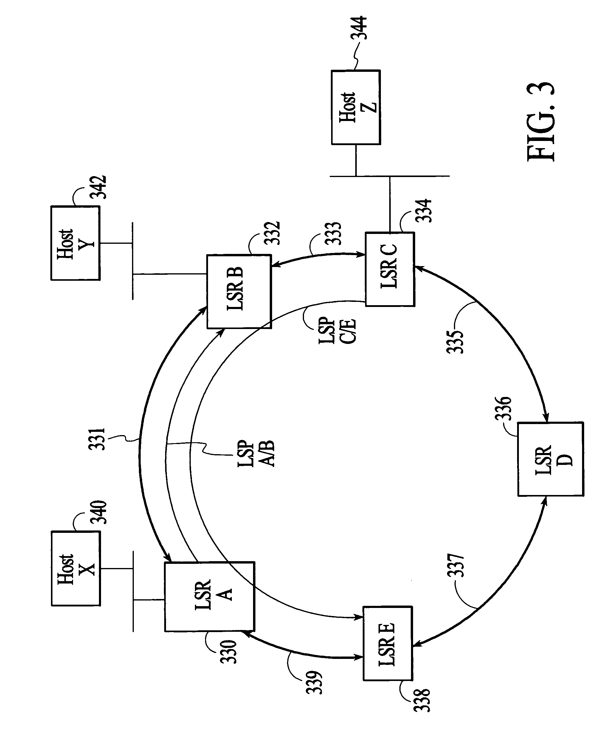
[0046]FIG. 3 depicts a group of network nodes 330, 332, 334, 336, and 338 that are connected by transmission links 331, 333, 335, 337, and 339 to form a ring. In the embodiment of FIG. 3, all of the network nodes on the ring support label switching, for example, the MPLS protocol that is published by the IETF, and are referred to herein as label switch routers (LSRs). All of the LSRs on the ring form an MPLS domain. Each of the LSRs on the ring has a right side neighbor and a left side neighbor, where for purposes of this description a neighbor LSR is defined as a directly adjacent LSR and left and right are defined at each LSR relative to a person standing at the LSR and facing the center of the ring. Each of the LSRs may be connected to other network nodes that are not part of the MPLS domain. For example, LSR A 330 is connected to Host X 340, LSR B 332 is connected to Host Y 342, and LSR C 334 is connected to Host Z 344. In the embodiment of FIG. 3, the links between neighbor LSR...


PUM


Abstract

A working label switched path (LSP) between neighbor label switched routers (LSRs) in a ring network that utilizes label switching is protected by an LSP that connects the neighbor LSRs of the working LSP in an opposite direction to the working LSP. If the working LSP fails, then packets are switched to the protection LSP. Switched packets traverse the protection LSP until they reach the neighbor LSR that they would have reached had the packets traversed the working LSP. Time-to-live (TTL) values of packets that traverse the protection LSP are adjusted to account for the number of hops on the protection LSP so that the TTL values of the packets are the same after traversing the protection LSP as they would have been had they traversed the working LSP. After traversing the protection LSP packets can be switched back to the working LSP or switched to a next hop LSP.

Description

CROSS REFERENCE TO RELATED APPLICATION [0001] The present application is related to a prior application Ser. No. 09 / 865,035 filed May 24, 2001. [0002] This is a Continuation of copending application Ser. No. 10 / 021,754, filed on Dec. 12, 2001, the entire disclosure of which is incorporated herein by reference.FIELD OF THE INVENTION [0003] The invention relates to label switching, and more particularly to a method and system for providing failure protection in a ring network that utilizes label switching. BACKGROUND OF THE INVENTION [0004] In packet-switched networks, packets traveling from a source address to a destination address may be transmitted through many intermediate network nodes, such as switches or routers. Intermediate network nodes that receive packets headed for the destination address utilize look-up tables to determine the next hop for the packets. Label switching is a technique that has been developed to expedite the look-up process at each hop as packets travel fro...

Claims


Application Information

Patent Timeline
Patent Type & Authority Applications(United States)
IPC IPC(8): H04L12/26H04L12/437H04L45/02H04L45/122H04L45/24H04L45/28H04L45/50
CPCH04L12/437H04L45/00H04L45/10H04L45/20H04L45/22H04L45/28H04L45/50H04L45/502
Inventor BEHZADI, BEHNAM
Owner LUCENT TECH INC
Why Eureka
Try Eureka