Optical network terminator

a network terminator and optical network technology, applied in the field of optical data communication, can solve the problems of increasing losses, increasing losses, and increasing losses of passive optical devices, and achieve the effect of removing unwanted nois

Inactive Publication Date: 2006-09-12
VENTURE LENDING & LEASING III
View PDF26 Cites 50 Cited by
  • Summary
  • Abstract
  • Description
  • Claims
  • Application Information

AI Technical Summary

Benefits of technology

[0033]There is still further provided in accordance with the present invention a method of optically terminating an optical network having one or more channels, the method comprising the steps of receiving an input optical sign

Problems solved by technology

A problem associated with such types of optical networks is the losses incurred from the passive optical devices, such as filters, couplers, multiplexers, etc.
The losses, which exist at every node on the network, can increase as the number of optical components increases, such as in networks with large numbers of nodes,
The use of optical amplifiers, however, is problematic.
In addition, the optical amplifiers add noise to the line in addition to the signal and to the noise already present.
In an optical ring network, however, the use of active optical amplifiers causes noise accumulation from amplifier spontaneous emissions (ASE) and from other noise sources as well, and is commonly referred to as noise creep.
Considering even small amounts of amplifier noise, it can be seen that the effects of noise creep can amount to significant levels

Method used


Image

  • Optical network terminator
  • Optical network terminator
  • Optical network terminator

Examples


Embodiment Construction

Notation Used Throughout

[0045]

The following notation is used throughout this document.TermDefinitionADOMAdd Drop Optical MultiplexerASEAmplifier Spontaneous EmissionASICApplication Specific Integrated CircuitCPUCentral Processing UnitDSPDigital Signal ProcessorWWDMWide Wavelength Division MultiplexingCWDMCoarse Wavelength Division MultiplexingDWDMDense Wavelength Division MultiplexingEDFAErbium Doped Fiber AmplifiersEEROMElectrically Erasable Read Only MemoryFBGFiber Bragg GratingFPGAField Programmable Gate ArrayIPInternet ProtocolLANLocal Area NetworkMANMetropolitan Area NetworkOADMOptical Add Drop MultiplexerOBPFOptical Band Pass FilterOEOOptical Electrical OpticalRAMRandom Access MemoryROMRead Only MemoryWANWide Area NetworkWDMWavelength Division Multiplexing

DETAILED DESCRIPTION OF THE INVENTION

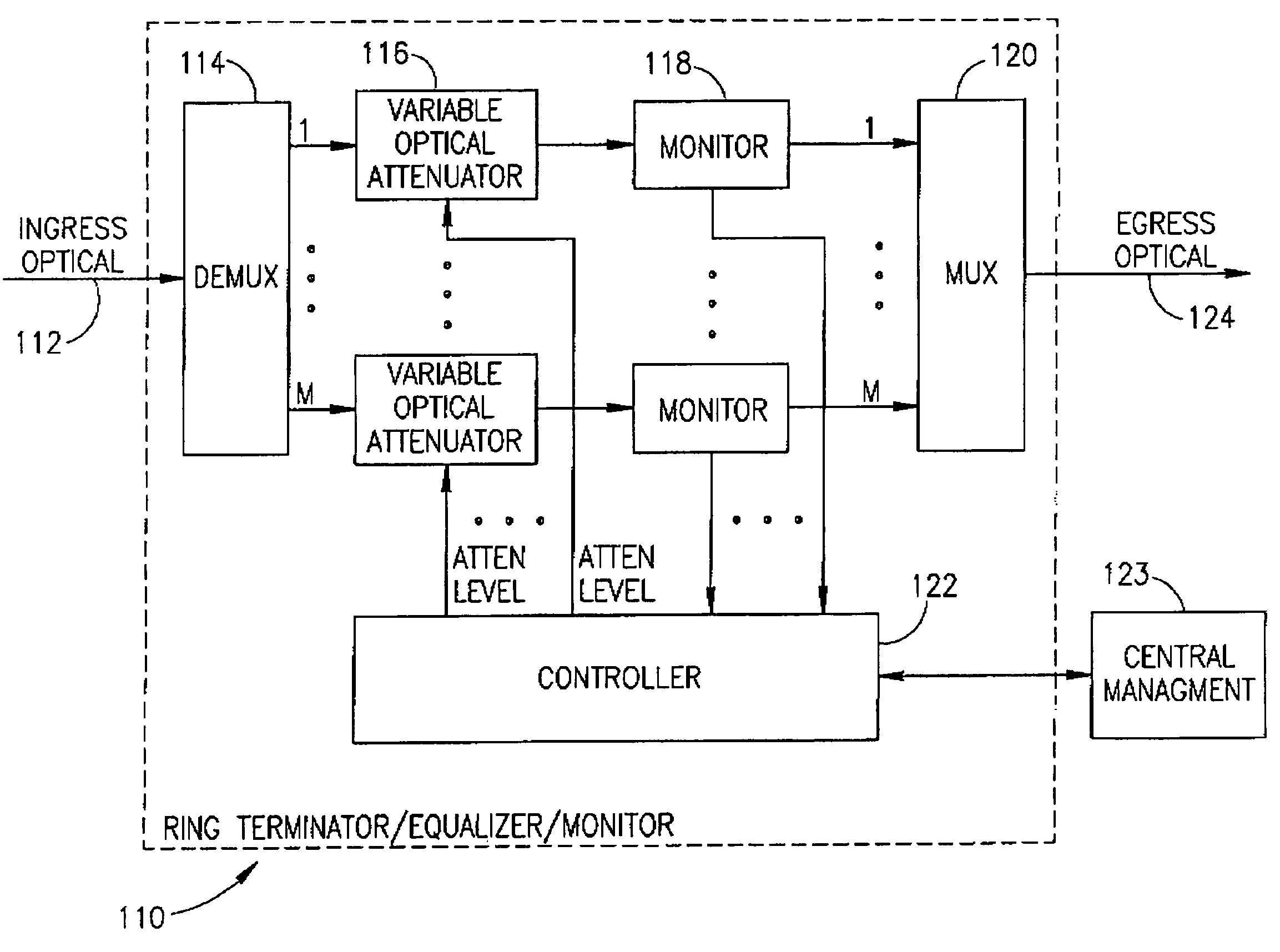
[0046]The present invention comprises an optical network terminator for terminating an optical network and removing unwanted noise accumulation. The invention is applicable to optical netw...


PUM


Abstract

An optical network terminator for terminating and reducing the accumulated noise in optical networks, particularly ring based networks. The terminator eliminates problems of noise accumulation from amplifier spontaneous emission (ASE), thermal noise, etc., while providing bi-directional communications in the optical network. The optical network may have any topology including ring, star, mesh, point-to-point, etc. In the case of an optical ring, the ring is broken and an optical terminator is placed in line therewith. The optical network terminator includes a filer such as an optical demultiplexer/multiplexer or Fiber Bragg Grating (FBG) based filter. Each individual wavelength of light is filtered and a multi-wavelength optical output is generated whereby the noise accumulation is removed. Each channel is adapted to only pass a band-limited signal around the center frequency corresponding to the wavelengths supported by the particular optical ring network. Channel equalization uses variable optical attenuators and monitors in line with each channel. Channels currently not in use may be disconnected from the ring remotely by setting the corresponding optical attenuator to a low enough level.

Description

FIELD OF THE INVENTION[0001]The present invention relates generally to optical data communications and more particularly relates to an optical network terminator for terminating an optical based network.BACKGROUND OF THE INVENTION[0002]Optical communication systems are becoming more and more widespread mainly due to their very large information carrying bandwidths. The growth and diversity of lightwave networks, such as Wavelength Division Multiplexed (WDM) networks are placing new demands on all aspects of optical networks including, for example, capacity management and provisioning, maintenance, and reliable and robust operation. In addition, the current trend in many carrier networks is to implement standard IP based networks to achieve convergence of traditionally separate voice and data networks. To this end, the use of Ethernet based equipment in implementing carrier networks is becoming increasingly common.[0003]Currently, high capacity optical networks are constructed as rin...

Claims


Application Information

Patent Timeline
IPC IPC(8): H04B10/00H04B10/02H04B10/04H04B10/08H04B10/20H04J14/02
CPCH04B10/25073H04J14/0201H04J14/0221H04J14/0246H04J14/0283H04B2210/258H04J14/0282H04J14/0284H04J14/0227
Inventor LICHTMAN, EYALHENDELL, ERIK
Owner VENTURE LENDING & LEASING III
Why Eureka
Try Eureka