Autoprotected optical communication ring network

a technology of optical communication ring network and protection mechanism, which is applied in the direction of multiplex communication, transmission monitoring, instruments, etc., can solve the problems of temporary failure of all other working channels, inability to protect more than n channels, and inability to have different protection mechanisms

Inactive Publication Date: 2006-07-04
CISCO TECH INC
View PDF12 Cites 49 Cited by
  • Summary
  • Abstract
  • Description
  • Claims
  • Application Information

AI Technical Summary

Benefits of technology

[0018]The Applicant proposes, with the present invention, an improved type of shared protection technique, in which re-routing operations are performed only at the nodes which terminate affected links and only on the failed channels, thus avoiding the drawbacks related, to re-routing operations on the multiplex section, and by using an optical reconfigurable connection mechanism which allows the omission of a SDH layer protection mechanism. Moreover, the failure control is performed at the channel level instead of at the multiplex section level, thus avoiding the above mentioned drawbacks.
[0020]The protection technique of the invention provides the following advantages:
[0021]By operating protection at the channel level, it is possible to provide optical protection to a selected subset of optical channels and leave to other layers (e.g. SDH) or to other optical protection mechanisms the protection of the remaining channels.
[0022]Using an optical re-routing technique, it is possible to omit the SDH protection layer, thus simplifying the node structure and allowing a direct connection to the ring network for clients using different protocols (possibly unprotected) like ATM, IP, etc. The proposed protection technique is therefore compatible with every client electronic transmission protocol.
[0028]Differently from the Optical Multiplex Section Shared Protection scheme proposed in U.S. Pat. No. 5,647,035, switching operations are performed externally to the network, and then no transitories are present. In particular, switching of the single channel is performed, as described below, between the receiving and the transmitting transponders and, therefore, the multiplexed optical flux conditions at the input of the node amplifier are substantially unchanged and then sudden power variations inside the network are avoided.

Problems solved by technology

The Applicant observes that; although this method provides a double capacity with respect to the previous technique, with N wavelengths it is still not possible to protect more than N channels.
Moreover, the Applicant further observes that, in this case, it is not possible to have different protection mechanisms (i.e. protection at different layers) for different channels, and that the optical path after a protection reconfiguration can be longer than the ring circumference.
Furthermore, the Applicant observes that, in the Optical Multiplex Section Shared Protection, since the failure control is performed at the multiplex section level, a failure on a single optical channel (e.g. when a node transmitter is damaged) can be either ignored or it can cause the reconfiguration of all the traffic thus causing a temporary failure on all the other working channels.
In case of a transoceanic application, this protection solution may lead, due to loopbacks, to restoration transmission paths that would cross the ocean three times.
The Applicant observed that, in this case, as in the protection solution of U.S. Pat. No. 5,647,035, the failure control is over the entire optical multiplex section and, therefore, a failure on a single optical channel may be either ignored or it can cause the reconfiguration of all the traffic thus causing a temporary failure on all the other working channels.

Method used


Image

  • Autoprotected optical communication ring network
  • Autoprotected optical communication ring network
  • Autoprotected optical communication ring network

Examples


Embodiment Construction

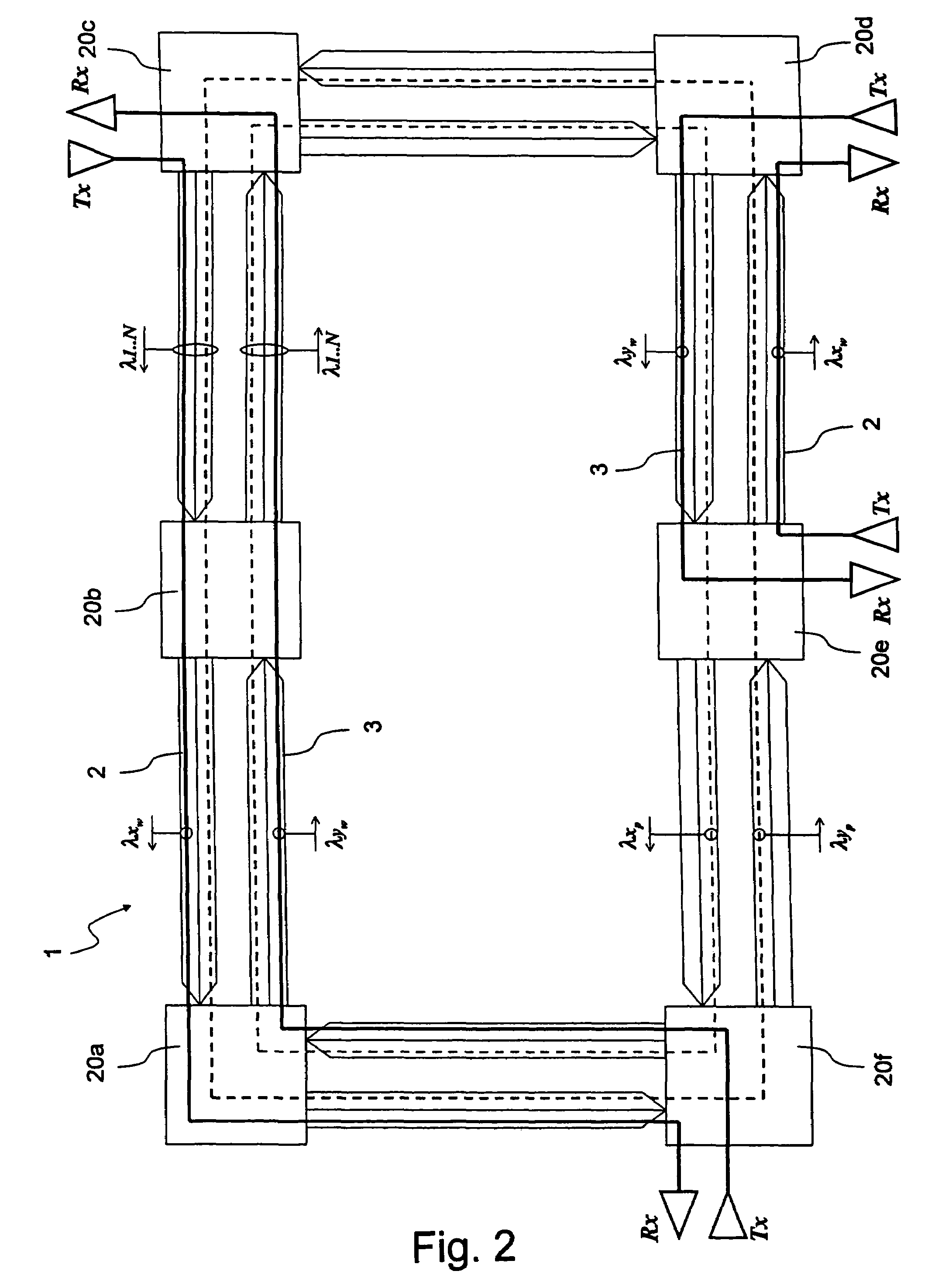
[0126]Schematically shown in FIG. 2 is an optical communication ring network 1 according to the present invention. NetWork 1 includes a first and a second optical fiber ring 2, 3 defining respective optical carriers having opposite transmission directions, and a plurality of nodes 20a–20f for adding and dropping optical signals, positioned along the first and the second ring 2, 3.

[0127]Network 1 is adapted to be used for both terrestrial transmissions and transoceanic transmissions. For long-haul transmissions, in particular for transoceanic transmissions, network 1 is preferably provided with line optical amplifiers and / or boosters and / or preamplifiers (not shown).

[0128]In the schematic representation of FIG. 2, rings 2, 3 define an external and, respectively, an internal ring, having a counter-clockwise transmission direction and, respectively, a clockwise transmission direction. The nodes in network 1 have been chosen in number of six just by way of example and the present invent...


PUM


Abstract

An autoprotected optical communication ring network includes a first and a second optical carrier having opposite transmission directions and a plurality of optically reconfigurable nodes optically connected along the first and the second optical carrier and adapted to communicate in pairs on links susceptible to failure, the ring network having a normal operative condition in which the nodes of each pair are optically configured so as to exchange optical signals on a working arc path at a respective first wavelength (λx) on the first carrier and at a respective second wavelength (λy) different from the first wavelength (λx) on the second carrier, the working path having a complementary arc path defining a protection arc path in which the first wavelength (λx) on the first carrier and the second wavelength (λy) on the second carrier can be used for further links.

Description

CROSS-REFERENCE TO RELATED APPLICATIONS[0001]This application is related to and claims benefit of priority to European Patent Application No. 01-11594.8, filed 31 May 2000, is incorporated herein by reference.Technical Field of the Invention[0002]The present invention relates to an autoprotected optical communication ring network, in particular a WDM (Wavelength Division Multiplexing) autoprotected optical communication ring network of the type including a plurality of nodes connected to each other in pairs by means of respective optical connections susceptible to failure, each connection comprising at least a first and a second optical carrier having opposite transmission directions.BACKGROUND OF THE INVENTION[0003]“Optical communication ring network” here means not only a communication network configured as a whole as a ring but, in general, any section of a network comprising a plurality of nodes and branches and arranged, at least temporarily, in a ring configuration.[0004]Speci...

Claims


Application Information

Patent Timeline
Patent Type & Authority Patents(United States)
IPC IPC(8): H04J14/02H04B10/08H04B10/14H04B10/24H04Q11/00
CPCH04J14/022H04J14/0283H04J14/0286H04Q11/0062H04J14/0295H04Q2011/0092H04Q2011/0081
Inventor ARECCO, FULVIOVISCARDI, VALERIOAPRILE, ALDO
Owner CISCO TECH INC
Why Eureka
Try Eureka